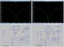
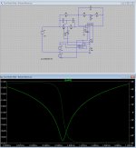
Demian, I was intrigued by your design since it would allow me to ignore the third IC for 20 dB (or 40dB) gain in Dick's design , and thereby avoid any extra added noise+THD. Since I have already made my resistor rotary switches I ran your circuitry in LTSpice and compared the output with a modified Moore circuitry (see picture) where I added feedback resistors to U1 and U2 giving the output at U1 20dB+20dB=40dB gain of the harmonics, a result similar to yours. The notch is however deeper (goes down to -60 dB) and somewhat sharper. The band at 0dB is about the same in both circuits (about 5Hz).
It appears to me that the blunter bottom of your notch is due to addition of R10 and the change of R1 and C1 values from the otherwise "standard" 2/1 relationship. Although your circuit may be great for a one-frequency notch filter I wonder if also R10 has to be tuned (along with R1,R2 and R5) in order to cover other frequencies?
I also did a quick noise analysis of your circuit and it appears to me that lower current noise in U1 (due to lower values of R1 and R5) is more than compensated by higher voltage noise in U1 and U2 due to the high gain. I'm therefore wondering, if by adding a 40dB gain IC (using AD797) to the output of the modded Moore circuit, wouldn't it give me the best of both worlds, a tunable (20Hz to 20kHz) filter and 40dB gain of the harmonics.
Attachments
The circuit I tweaked has a very specific application actually. I'm banging into the limits of the Shibasoku analyzer with these latest uber low distortion oscillators. Boosting the harmonics and keeping enough of the fundamental allows me to see harmonics at -140 to -170(? wishful thinking) which are below the internal distortions of any analyzer. The noise will be less of an issue after the FFT averaging. I can even try coherent averaging with the locking inputs on some of these oscillators. I only need 1 or 2 frequencies with this. Its not for use with normal amps and preamps. They just don't get this low in distortion. Even with the network spread out on the bench the FFT was both accurate and useful. THD+N won't get below about -115 dB no matter how hard we try.
There is one limitation still I'm thinking through. If I have a source with -150 dB harmonics (Jens', Victor's or David's oscillator for example) will the distortion of the main amplifier mask it? The amp has 40 dB of gain. Its distortion is rated at about -140 dB at unity gain. At +40 that would be about -100 dB distortion. So will the distortion from the reduced fundamental be as high at the target distortion products? Its seems likely to be an issue. I will know soon.
Optimizing the noise of the main opamp to match the notch network is key number 1. The noise contribution of the Q multiplier opamp is really important since its output feeds directly into the network. With a 100 Ohm source (the divider) the lowest voltage noise is critical. Adding an amp after the network won't get lower noise and will probably be noisier since its noise will add the the input noise with a unity gain follower in front.
With the higher resistance of your network the OPA134 is a good choice but the overall noise is limited by the network resistances.
Having a known depth to the notch that is not critical makes it much easier to tune to and use. This is the principle of the Shibasoku and it does work pretty well.
There is one limitation still I'm thinking through. If I have a source with -150 dB harmonics (Jens', Victor's or David's oscillator for example) will the distortion of the main amplifier mask it? The amp has 40 dB of gain. Its distortion is rated at about -140 dB at unity gain. At +40 that would be about -100 dB distortion. So will the distortion from the reduced fundamental be as high at the target distortion products? Its seems likely to be an issue. I will know soon.
-40dBV down from 0dBV is 10mV rms. I don't think it's an issue. All the 40dB of gain does is raise the noise and existing distortion but the ratios stay the same. The small amount of distortion 10mV raised in the post amp is miles apart from what your measuring. It's -140dB at unity what is it at 10mVrms (-40dBV), -180dB?
There is one limitation still I'm thinking through. If I have a source with -150 dB harmonics (Jens', Victor's or David's oscillator for example) will the distortion of the main amplifier mask it? The amp has 40 dB of gain. Its distortion is rated at about -140 dB at unity gain. At +40 that would be about -100 dB distortion. So will the distortion from the reduced fundamental be as high at the target distortion products? Its seems likely to be an issue. I will know soon.
As David noted, you need to consider the output level of the opamp. The -140 dB figure you quote is probably for about 3 Vrms. Now let's say you feed the passive notch filter with 3 Vrms and it has 60 dB fundamentual attenuation. So the output of the filter is 3 mVrms, and the output of the opamp 300 mVrms.
The distortion-vs-level behaviour of the opamp cannot be predicted exactly, but a useful first estimate is that the (relative) distortion increases proportionally with level. This means that at 300 mVrms output and with 40 dB noise gain, the opamp performs with about -120 dB. With the 60 dB notch, this makes -180 dB referred to the input.
But this is a simplified view--a more detailed analysis would also need to consider the output current (and not just output voltage) swing.
Fortunately at 40 dB gain, it is easy to make a very high performance composite opamp. Just put two opamps right in series, with an appropriate overall RC feedback network (see sboa015.pdf, figure 9). A proper implementation of this concept will have ridiculously low distortion contribution, limited mostly by the passives in the feedback network.
Samuel
Bridged T equalizer for Twin T notch
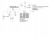
Here is an alternative to TT Q multiplier and the use of positive feedback.
Like Sallen key filters the use of positive feedback is a major contributor of noise.
The circuit eliminates the need for positive feedback and enables the use of lower TT Q and bridged T EQ all done with a single op amp. Added pass band gain will requires an additional amplifier. The post amp can be an inverting type using low R values and one of the sub 1nV low noise op amps. The depth of the notch is controlled with a single resistor which has no effect on tuning frequency. The Q of the equalizer is set by capacitor ratio and the Q sets the pass band flatness. The EQ is tuned to the fundamental of the TT. The impedance of the EQ is scalable. The EQ is independent from the TT network. The two networks are isolated by the amplifier.
Attachments
Can you post your spice file? Its very interesting and needs to be breadboarded. How close do the two networks need to be? If one is 5% of does it still work?
For a single frequency using two tuned networks is fine but it gets cumbersome when you want more frequencies.
If I do my sums right (always questionable) correcting for input equivalent noise (divide by 100) my earlier design with 2 LME49990 opamps gets 1.15 uV in the 30 KHz band. I think its mostly the lower resistor values coupled with really low noise opamps. I should have the real thing running very soon. I just finished trimming the caps to .02%.
Excellent post David. I took your proposal and implemented it into my circuit with positive feedback and tweaked the values to achieve a controlled 40dB notch with about the same Q value. With the feedback option I can also get the notch down 98dB by varying resistor R7. I did also counteract the feedback resistor noise by dividing resistor values by 100 and multiplying cap values by 100. Haven't run noise calculations yet but I guess it won't be very much higher than yours.
Have you by any chance measured your output noise using AD8429?
Have you by any chance measured your output noise using AD8429?
Attachments
Last edited:
So right, Demian, and they won't be pretty.... Now the need for an unbelievably good buffer amp to drive the filter appears again. I agree that a great composite amp is likely the best course. I hope one of the smart folks here can actually build one that won't add noticeable distortion or noise... I'm especially hopeful that David can bring his skill to bear on this.
Nice work David. Did you design this or was this implemented elsewhere?
Good Stuff!
It's not my concept but it is my design. I just put it together today in spice.
I've used both circuits independently, just brought them together.
If someone want's to do the prof of concept by all means put one together and let use know how it goes.
Excellent post David. I took your proposal and implemented it into my circuit with positive feedback and tweaked the values to achieve a controlled 40dB notch with about the same Q value. With the feedback option I can also get the notch down 98dB by varying resistor R7. I did also counteract the feedback resistor noise by dividing resistor values by 100 and multiplying cap values by 100. Haven't run noise calculations yet but I guess it won't be very much higher than yours.
Have you by any chance measured your output noise using AD8429?
C3 and C4 shown in the bridge T section is not correct per Davids formula,
Can you post your spice file? Its very interesting and needs to be breadboarded. How close do the two networks need to be? If one is 5% of does it still work?
For a single frequency using two tuned networks is fine but it gets cumbersome when you want more frequencies.
If I do my sums right (always questionable) correcting for input equivalent noise (divide by 100) my earlier design with 2 LME49990 opamps gets 1.15 uV in the 30 KHz band. I think its mostly the lower resistor values coupled with really low noise opamps. I should have the real thing running very soon. I just finished trimming the caps to .02%.
Yes I can post the spice files.
The center frequencies can be a bit off but if they're to far apart the band pass will be lumpy. It's a low Q bandpass transfer. If the band pass envelop is over one of the notch shoulders instead of center of the notch, I think you can visualize what this would look like. You can use nearest standard value caps and still get good results. The lower Q of both networks lowers the sensitivity by a huge amount. Less fussy on precision parts.
The component values I used were arbitrary. Use what ever works best.
Last edited:
Excellent post David. I took your proposal and implemented it into my circuit with positive feedback and tweaked the values to achieve a controlled 40dB notch with about the same Q value. With the feedback option I can also get the notch down 98dB by varying resistor R7. I did also counteract the feedback resistor noise by dividing resistor values by 100 and multiplying cap values by 100. Haven't run noise calculations yet but I guess it won't be very much higher than yours.
Have you by any chance measured your output noise using AD8429?
No measurements. I haven't built it and don't have a model for that op amp.
So right, Demian, and they won't be pretty.... Now the need for an unbelievably good buffer amp to drive the filter appears again. I agree that a great composite amp is likely the best course. I hope one of the smart folks here can actually build one that won't add noticeable distortion or noise... I'm especially hopeful that David can bring his skill to bear on this.
Yes well it all takes time then doesn't it. I'll get to it.
- Status
- This old topic is closed. If you want to reopen this topic, contact a moderator using the "Report Post" button.
- Home
- Design & Build
- Equipment & Tools
- Build -- Active Twin-T notch filter for distortion analysis