Sorry if this has been discussed already, but why not a state variable notch filter, since Mr. Marsh thought it was great on his website?
http://www.analog.com/static/imported-files/tutorials/MT-223.pdf
http://www.analog.com/static/imported-files/tutorials/MT-223.pdf
Sorry if this has been discussed already, but why not a state variable notch filter, since Mr. Marsh thought it was great on his website?
http://www.analog.com/static/imported-files/tutorials/MT-223.pdf
Boards are already available. I have one and so does Larry Burk.
Larry's might be easier to work with. Mine where designed such that they can be used for other purposes besides the twin t. I can make the gerber files available.
Boards are already available. I have one and so does Larry Burk.
Larry's might be easier to work with. Mine where designed such that they can be used for other purposes besides the twin t. I can make the gerber files available.
OK, is it a state variable notch filter, or a twin-t? Either way, designing a board for this looks to be trivial.
I was going to offer actual boards ready to use, for about $20 each shipped in the US, but I guess it's not necessary.
Sorry if this has been discussed already, but why not a state variable notch filter, since Mr. Marsh thought it was great on his website?
[/url]
Hardly his website.
Davada,
Can you please publish the schematic, or tell us where we can find them?
Tks,
Paul
Hi Paul,
You can find schematics for the Twin T here at Dick Moore's web pages.
Active Twin-T notch filter
OK, is it a state variable notch filter, or a twin-t? Either way, designing a board for this looks to be trivial.
I was going to offer actual boards ready to use, for about $20 each shipped in the US, but I guess it's not necessary.
I'd buy one if fully loaded and ready to use. But would like variable type the most, if possible.
THx-RNMarsh
Why not a SV notch filter?
The reasons are simple:
1) the Twin-T is essentially a passive filter that has nearly infinite null when carefully tuned -- the null is independent of all associated electronics.
2) The SV however depends on summing in an opamp. The practical result is that altho the SV can be truly excellent, all kinds of subsidiary issues of opamp choice, power supply cleanliness, shielding, etc come into play.
3) In general, the noise floor and the THD of the active T-T are lower than in all other active designs, especially those that depend on algebraic operations, such as summing, with opamps.
I'm not saying there are not similar issues for the T-T, but to a much lesser degree, and the T-T can easily be battery operated, which solves a myriad of problems. The active T-T uses the opamp for buffering and positive feedback that raises the filter Q, without affecting tuning frequency or depth. Sometimes simplicity is a virtue.
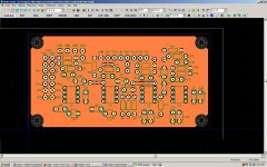
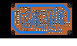
The boards don't have any of the tuning elements on them just the amplifiers. Both are DIP and through hole parts.
tantalum were used for bypassing but I had a lot of trouble with them shorting. I can change footprint to elec.
There's extra op amps for gain boost or other general use. If thet're not needed leave them off.
tantalum were used for bypassing but I had a lot of trouble with them shorting. I can change footprint to elec.
There's extra op amps for gain boost or other general use. If thet're not needed leave them off.
Attachments
Last edited:
Hi David, I was aware and have been through that article, but thanks anyway.
The schematic from Dick is not one that can be used without some detailed parts and layout knowledge that I don't have. That was the missing link I was after. You now shared the layouts in a later post but without the matching schematic it's still a bit of a puzzle. They look very professional to me though! I'm not a layout wiz, let alone one for these highly sensitive designs. I'll give it a try on a prototype pcb board first, just to get it all working, then we'll see what needs to be done.
Again thanks for sharing!
Paul
Hardly his website.
OK, well I don't pay attention very well either.
Hi David, I was aware and have been through that article, but thanks anyway.
The schematic from Dick is not one that can be used without some detailed parts and layout knowledge that I don't have. That was the missing link I was after. You now shared the layouts in a later post but without the matching schematic it's still a bit of a puzzle. They look very professional to me though! I'm not a layout wiz, let alone one for these highly sensitive designs. I'll give it a try on a prototype pcb board first, just to get it all working, then we'll see what needs to be done.
Again thanks for sharing!
Paul
The layout isn't that fussy. A PCB is more a convenience. Dick did his on perfboard (Veroboard) and it works fine. I didn't see any improvement going to a PCB. It just looks nice.
I have just finished building the twin notch filter from the schematic posted by Dick. At first it didn't work at all but then I suspected that a possible missing joint of two connections (right after the input) in the schematic might be the culprit. After a quick question to Dick he confirmed that it was the case and his schematic was updated.
I am now playing around with testing different kinds and values of pots for achieving a high Q notch (>100 dB). So far I've found that the best solution is to have two pots in series on both ladder 1 and 2 ( one Fine and one Super Fine). The Fine pot is one-turn 500 ohm conductive plastic (low noise) and the Super Fine is a 10-turn 100 ohm wire wound Helipot. I even tried a third 5 ohm pot but that didn't improve anything.
Using a high quality variable frequency oscillator (the Cordell oscillator) at various frequencies I noticed that the highest Q can only be achieved at exactly 22 specific frequencies within each frequency range. A few Hz off and the notch will be shallower. Looking at the schematic I suspect that 3 pots might be needed instead of two. The third leg of the resistor ladder has a 249 ohm resistor rather than a pot. According to the theory for this notch filter the resistance value R of the first and the third ladder should be identical whereas the second ladder should have exactly 1/2 R resistance. This relationship is correct for the 22 frequencies (assuming perfect matching 0-tolerance resistors and capacitors) matching the 22 switch positions but becomes disturbed for all other frequencies since the two Fine Pots need to be adjusted for frequency tuning (The values of resistor ladder 1 <> ladder 3).
The result is that in order to achieve consistent and very deep nulls the oscillator has to be tuned to match one of the specific 22 frequencies of the notch filter. I would prefer to have it the other way around so that the notch filter could be tuned to any frequency with equal efficiency. An obvious solution would be to have three fine precision pots (replacing the 249 ohm resistor with a pot) with maybe using 1 and 3 in parallel as one pot. I would like to hear from anyone who has tried this or may have another solution to this issue.

@tkollen -- I can tune to below 100dB notch (very briefly) at any frequency -- note that the tuning is temperature and vibration sensitive, not to mention contact resistance, etc; working in the 1ppm area is challenging to say the least.
I'm really not sure what you are seeing, but it may have to do with your spectrum analyzer settings -- the "bucket" frequency width varies depending on number of samples and max frequency, so I think you are tuning to the centers of the SA "bucket" resolution. Try increasing the number of samples to several hundred thousand and limit your sampling frequency to 44.1kHz for around a 1kHz notch. Using two pots in each leg is a good addition to increase both range and fineness, and having pots in the third leg is also helpful, especially at the small resistance end of a range. A nice combo would be 1k and 100 ohms in series -- these are pretty standard values that are readily available.
I'm really not sure what you are seeing, but it may have to do with your spectrum analyzer settings -- the "bucket" frequency width varies depending on number of samples and max frequency, so I think you are tuning to the centers of the SA "bucket" resolution. Try increasing the number of samples to several hundred thousand and limit your sampling frequency to 44.1kHz for around a 1kHz notch. Using two pots in each leg is a good addition to increase both range and fineness, and having pots in the third leg is also helpful, especially at the small resistance end of a range. A nice combo would be 1k and 100 ohms in series -- these are pretty standard values that are readily available.
It's cool this thread picked up some activity.
I finally moved my notch filter from my prototype board to an enclosure. Here are a few photos. Thanks again Dick for this design. I tested it and it is working great.
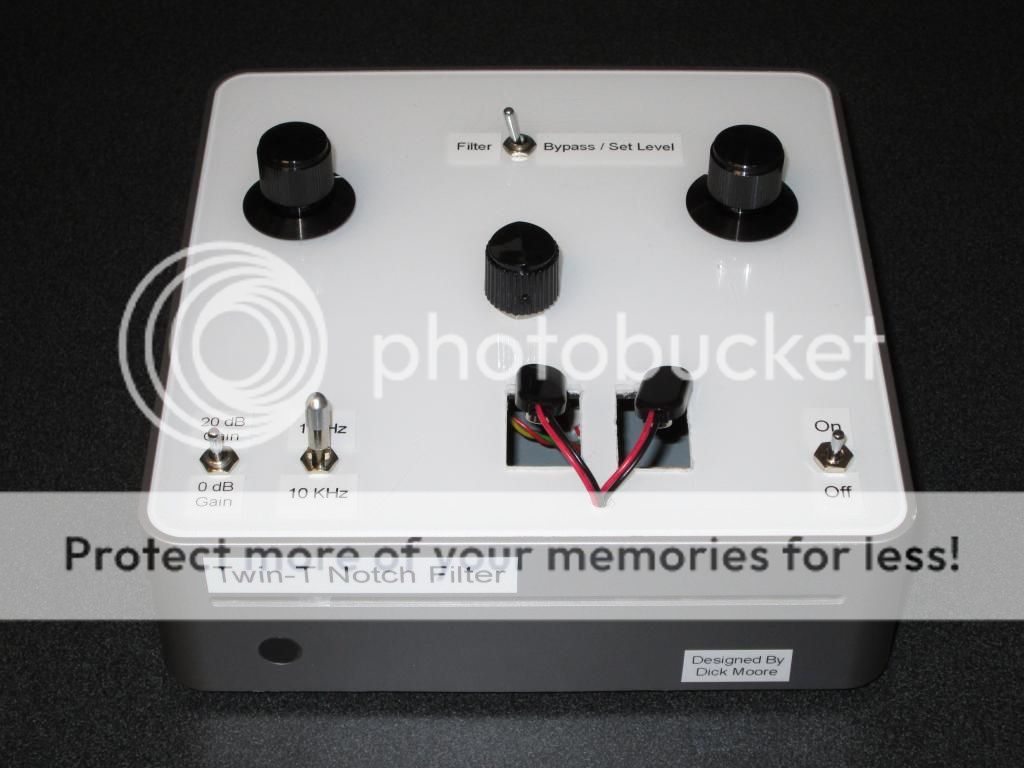
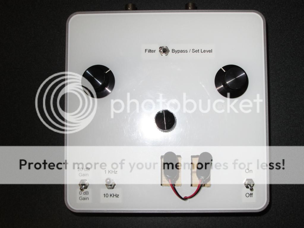
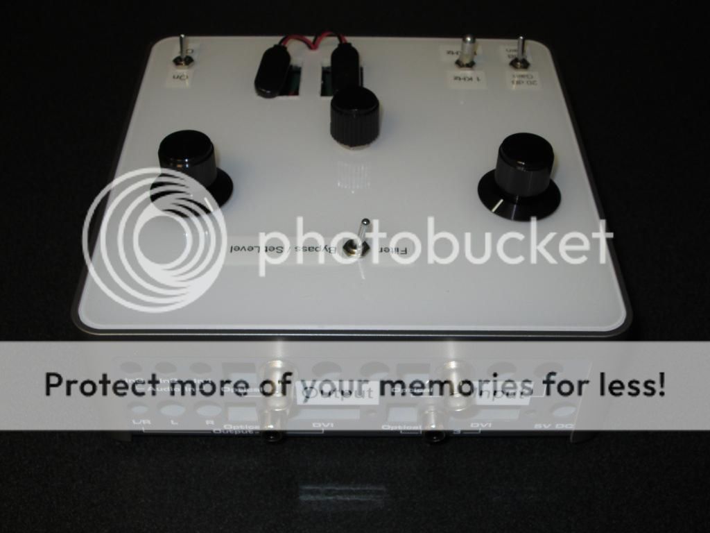
tkollen, what caps did you end up using in your filter? Do you have the vendor and part numbers you would be willing to share?
Dave
I finally moved my notch filter from my prototype board to an enclosure. Here are a few photos. Thanks again Dick for this design. I tested it and it is working great.


tkollen, what caps did you end up using in your filter? Do you have the vendor and part numbers you would be willing to share?
Dave
- Status
- This old topic is closed. If you want to reopen this topic, contact a moderator using the "Report Post" button.
- Home
- Design & Build
- Equipment & Tools
- Build -- Active Twin-T notch filter for distortion analysis