Bill of Material for Dick Moore's Active Twin-T
Does anyone have a complete Bill of Material for Dick Moore's Active Twin-T?
I can not read the schematic, my eyes are not what they used to be.
Please post the Bill of Material to this thread. That was we would have
a source for this information.
Dick Moore does not have a BOM on his WEB site, I asked.
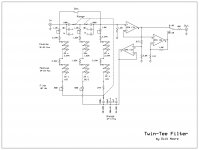
This not a BOM but I believe it is a readable schematic of Dick'sTee.
Attachments
Hi all -- Were I to build my Twin-T today, I would build it for two or three fixed frequencies with a small tuning range for best fit to gear under test. This type of construction will result in a much simpler and more economical build than my original, which covers the whole 20Hz to 20kHz range and uses a LOT of parts.
With two or three frequencies, one set of resistors and tuning pots can be used, with frequency switching done by switching capacitor sets -- this hugely simplifies the build.
If building for analyzing audio gear, I would choose 1kHz, 10kHz, and 20kHz for a three-freq build, and 1k and 20k for a two-freq build.
For those of you comfortable with building from scratch and using the simple design equations (the only kind I'm comfortable with), then my web page likely has everything you need to do a simple build. I never intended the Twin-T to be a kit-type project with all decisions made a priori -- you gotta work through some stuff.
Thx DDB for posting the schematic -- I'll look at it to see if I recognize it right away. Looks good to me. Thanks again. Can I use that one for my site?
Best,
Dick
Last edited:
Yes you can but check for accuracy as it was just batted it out when I had difficulty reading the other one.Can I use that one for my site?
Does anyone know how important the distortion of the op-amps used in the filter are? I know Dick measured very little but curious if that varies significantly based on the chosen op-amp.
Absolutely the op amp chosen matters for both distortion and noise. But more importantly the
input Z of the op amp as it loads the network.
Looks like OPA827 or OPA1641 will be the best for U1 if it has to be a FET input. Can U2 be bipolar input?
I know Dick has tried a number of op amps. Check with him. I agree with your choices.
Dick favors the OPA134. The OPA1641 has lower noise.
The Positive feedback in the filter pushes the noise floor up so this is an area to be considered.
I built a quick prototype of the Dick's notch filter with parts on hand. I did build it with a fixed frequency of 1K for this prototype and caps from the drawer. I know these are not the preferred caps, but they were the correct values. I plan to now build the real thing with a 1K setting and 10 K setting. I determined that if I use a switch to change the cap values, I can easily go between the two notch frequencies.
Below are some images. I attribute the noisy notch loop response to the bench supplies I am using to supply the + / - 9 Volts. Also, the op amp is an all purpose 1458 I think. It's what was on hand.
Only question, when the notch is in the circuit, I loose about 1.4 dB. Is this normal? My resistors around the op-amp section are close, but not exact to Dick's schematic.
Feedback is welcome.
Thanks! Dave
Below are some images. I attribute the noisy notch loop response to the bench supplies I am using to supply the + / - 9 Volts. Also, the op amp is an all purpose 1458 I think. It's what was on hand.
Only question, when the notch is in the circuit, I loose about 1.4 dB. Is this normal?
My resistors around the op-amp section are close, but not exact to Dick's schematic.Feedback is welcome.
Thanks! Dave
An externally hosted image should be here but it was not working when we last tested it.
An externally hosted image should be here but it was not working when we last tested it.
An externally hosted image should be here but it was not working when we last tested it.
@skidave -- nice work -- pretty good results for a first pass. The noise is mostly line-frequency harmonics, usually from the power supplies and the unshielded board, but possibly from the generator too, maybe even mostly from the generator.
Now, about the loss of 1.4dB -- what is the source and what is it's output Z? Is the loss of 1.4dB at 100Hz, say, or at 4kHz, compared to the un-notched signal?
Also note that using the swept frequency response function in ARTA will not show the true notch depth, since is piece-wise and it may not actually be at the exact frequency of the notch, and also it doesn't stay there very long even if it is. The best way to know the notch depth is to use the spectrum analyzer and look at the peak of the fundamental compared to the un-notched signal.
You've definitely got the idea -- now just clean it up.
Thanks for the response Dick. I actually checked the response using my Tek SG-502 w/ a 600 ohm load. I set the Tek for 1KHz and tuned the notch for -30dB using a meter and watching on a scope. I then swept back and forth and saw the notch was tight, like it should be. The images I posted were using ARTA looped back with the notch in place.
When using the real instruments, I measured a 1.4 dB loss (pre notch frequency and post notch frequency) when the notch filter was in the signal path. (ARTA measured a 1.2 dB loss.) Do you have a loss w/ the notch filter in signal path?
Thanks!
Dave
When using the real instruments, I measured a 1.4 dB loss (pre notch frequency and post notch frequency) when the notch filter was in the signal path. (ARTA measured a 1.2 dB loss.) Do you have a loss w/ the notch filter in signal path?
Thanks!
Dave
Hi Dick,
I'm using 15.9K / 7.95K for the resistors and .010 uF / .020 uF combo. I don't have a high end cap checker, but the caps measure properly on my meter. I have to adjust the multi-turn pots to a bit lower than 15K to get the notch centered on 1KHz, so I'm thinking the cap values are a bit off. Also, the I did not have the exact resistor values for the divider for the feedback op amp. The 2K is 2.2K and the 215 is 268.
I found some Vishay Polypropylene .01uF caps in the cap drawer, so I might substitute them in the circuit.
Obviously, this circuit needs to be finalized w/ better parts. But doing well so far!
Dave
OK, Dave -- good job all around. The PP caps will be a very good choice. Your resistor values are not a problem, but in the final, be sure to use metal films.
I don't know why you have the insertion loss, but you need a FET input opamp at the output of the Twin-T -- the 1458 is completely unacceptable.... An OPA134/2134 is perfectly fine, and I think that will help, and try not to load the output of the opamp too much either.
I don't know why you have the insertion loss, but you need a FET input opamp at the output of the Twin-T -- the 1458 is completely unacceptable.... An OPA134/2134 is perfectly fine, and I think that will help, and try not to load the output of the opamp too much either.
Hi esl 63. I fine tuned mine on my bread board. I have a Mouser order that I need to finalize a few things for various projects. An enclosure and some better capacitors (tighter tolerance) will be for the notch filter. As it is on the bread board, I can achieve a -60dB notch like Dick Moore does. For what I DIY, -60 is just fine. I will post pictures once it is all done.
I like your user name. I have several Quad pieces, just not the ESLs. A family member had a nice pair of 57s a while ago.
Dave
I like your user name. I have several Quad pieces, just not the ESLs. A family member had a nice pair of 57s a while ago.
Dave
Hi all, love sitting on your knee taking it all in (for as far I can follow it). I just picked-up my old hobby again, and building a set of tools for audio analysis of mainly headphone amps and the likes.
After contemplating building the Cordell analyzer, I now switched horses to make it all a bit more simple - and more importantly, to the task. I have a 1KHz "Viktor" sinewave gen on order, and just ordered the parts for a version of the "Moore" Twin-T but tuned for 1KHz only. If that all works, I will add the 10KHz kit as well. As soon as I have all the parts and build the stuff I will report back.
I take it that there will be more folks that will have an interest in building the kit for actual use, rather than participating in the actual design.
I don't have the means to verify and test it all, but I hope that I can get some comments from this forum.
Thank you for my continued education!
- Status
- This old topic is closed. If you want to reopen this topic, contact a moderator using the "Report Post" button.
- Home
- Design & Build
- Equipment & Tools
- Build -- Active Twin-T notch filter for distortion analysis