Excellent post David. I took your proposal and implemented it into my circuit with positive feedback and tweaked the values to achieve a controlled 40dB notch with about the same Q value. With the feedback option I can also get the notch down 98dB by varying resistor R7. I did also counteract the feedback resistor noise by dividing resistor values by 100 and multiplying cap values by 100. Haven't run noise calculations yet but I guess it won't be very much higher than yours.
Have you by any chance measured your output noise using AD8429?
The idea is to eliminate the positive feedback all together. Both seems bit redundant.
But build it see how it goes.
Good news and bad news. I got the notch working and it works as predicted. A little tweaking and tuning and I have a -40 dB notch centered at the target frequency. Bad news is that the Q multiplier is actually creating distortion. I was getting more second harmonic than I should on the output. So I measured the input and the second harmonic is increased from below -140 to higher than -130 when the Q multiplier is active. In the passive mode all is fine except the notch depth is around 50 dB the way I have it tuned. I'll boost the gain to 50 dB so the analyzer/FFT have something to lock to. I still want to solve this issue. Perhaps its a problem with the q multiplier opamp running with output tied to the - input with no resistor. Tomorrow. . .
Scaling values by 10 and using the opa209 brought the noise down to 1.53uV in 30kHz. -161 dBV.

What if you used LC or LCR instead of RC for notch tuning freq? Lower noise? Higher Q?
THx-RNMarsh
Last edited:
Suitable L's for this will be large and distortion prone.
So far with all the tricks I'm still running into limits at around -150 or so. The good news is that the LME49990 is at around -135 dB on the harmonics as a 40 dB amp at 3V out. That would suggest -175 dB at unity gain if it were possible.
So far with all the tricks I'm still running into limits at around -150 or so. The good news is that the LME49990 is at around -135 dB on the harmonics as a 40 dB amp at 3V out. That would suggest -175 dB at unity gain if it were possible.
What if you used LC or LCR instead of RC for notch tuning freq? Lower noise? Higher Q?
THx-RNMarsh
The hum pick up is bad enough as it is. We would need shielded air core inductors and place the whole thing in an iron tub.
Now the need for an unbelievably good buffer amp to drive the filter appears again.
I do have good unity-gain buffer circuits in the drawer; what are the voltage/current driving requirements?
So far with all the tricks I'm still running into limits at around -150 dB or so.
What source are you using such that you can claim that the -150 dB is actually from the notch filter, and what is the drive level (perhaps I've missed this information)?
I see that you're using single passives for the filter elements. This is likely to limit distortion to -150 dB unless you're using rather low drive levels (I've seen Polystyrene caps with much higher distortion than this; 100 V C0Gs seem to be more consistent). As I think I've posted in related threads already, using series-parallel combinations is a very powerful technique to reduce distortion contribution from passives.
Samuel
what method are you using to get this level of resolution?............ I just finished trimming the caps to .02%.
I should have said matching, not absolute accuracy. I'm using an ESI Videobridge.what method are you using to get this level of resolution?
are you referring to aThose bridges have 6 digit resolution.
Samuel
Google found one for me. over $700. Not in my budget.ESI Videobridge.
I was hoping for a method, not an instrument.
Last edited:
What source are you using such that you can claim that the -150 dB is actually from the notch filter, and what is the drive level (perhaps I've missed this information)?
I see that you're using single passives for the filter elements. This is likely to limit distortion to -150 dB unless you're using rather low drive levels (I've seen Polystyrene caps with much higher distortion than this; 100 V C0Gs seem to be more consistent). As I think I've posted in related threads already, using series-parallel combinations is a very powerful technique to reduce distortion contribution from passives.
Samuel
I can't confirm either the notch or the different sources at this stage. The 725 shows harmonics at the -135 to -140 dB level that vary with different sources. The passive notch is an effort to see deeper into the harmonics but between noise (long enough FFT's start to run into drift issues) and internal distortions I don't have an improvement from this effort. The B&K is pretty high Z and I could not get below its limitations (2-3V sources are also a limitation).
I'll fire up the CLT-1 later and check the caps I'm using. The resistors are used in strings so using more is not an issue and I'll explore that, but only when the notch filter isn't causing more issues than it solves.
I do have good unity-gain buffer circuits in the drawer; what are the voltage/current driving requirements?
What source are you using such that you can claim that the -150 dB is actually from the notch filter, and what is the drive level (perhaps I've missed this information)?
I see that you're using single passives for the filter elements. This is likely to limit distortion to -150 dB unless you're using rather low drive levels (I've seen Polystyrene caps with much higher distortion than this; 100 V C0Gs seem to be more consistent). As I think I've posted in related threads already, using series-parallel combinations is a very powerful technique to reduce distortion contribution from passives.
Samuel
You did suggest this but didn't say what the combinations are. Equal values? etc.
Is there a formula?
I'll fire up the CLT-1 later and check the caps I'm using. The resistors are used in strings so using more is not an issue and I'll explore that, but only when the notch filter isn't causing more issues than it solves.
The "bad" caps I've seen usually show more 2nd harmonic than 3rd, so the CLT-1 might not reveal everything.
You did suggest this but didn't say what the combinations are. Equal values? etc. Is there a formula?
We want to reduce the voltage swing across capacitors and resistors, and the power dissipation of resistors. So series combinations help in any case; parallel combinations reduce just the power dissipation of resistors. If the required values for a pure series combination get inconvienient (e.g. too large for capacitors), a series-parallel arrangement is needed.
Samuel
-140dB is 100 parts per billion -- another 20dB, and we may have to switch from classical physics to quantum mechanics.... The uncertainties are piling up....
It's not the uncertainties I'm concerned with. It's amount of lifetime left to do it.
- Status
- This old topic is closed. If you want to reopen this topic, contact a moderator using the "Report Post" button.
- Home
- Design & Build
- Equipment & Tools
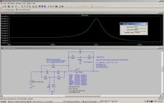
- Build -- Active Twin-T notch filter for distortion analysis