wapo - have you done any direct sound quality comparisons of your LDR volume control vs a highest quality switched attenuator (i.e. Vishay foil fixed series and switched parallel resistors, hard silver rotary switch)? I am sceptical that an LDR could match that, or even a cheaper version with switched parallel film resistors like Welwyns.
Last edited:
Well, all LDRs -- series and shunt -- should go to high resistance when power is removed from the LED. If one shunt is staying at low resistance that would cause the volume level to stay low because the signal is going to ground through that low shunt resistance.
You can mix and match the LDRs in any way that you wish for testing purposes. Only, to ensure proper channel tracking at low volumes you need the red dot LDRs in the red dot sockets. At medium volume settings it doesn't matter which device is in which socket. Remember to recalibrate.
BTW, how long does it take for a calibration to complete? It should be 12~15 minutes. If much longer, then at least one of the LDRs isn't responding properly
On that LDR that stays at low resistance, please check to ensure that the leads on the LDR are not physically pushed together to cause a short that causes the fixed low resistance.
That's an elegant build you've got there -- very nice, indeed. We need to figure this out.
If one shunt LDR is staying at a low resistance level and the leads are not physically touching, that high voltage episode probably put excessive current through the device and the LDR is probably bad. And yes, you could have damaged more than one LDR and the symptoms could be different.
Ah yes that makes total sense on why the volume is low then, so measuring them might not tell us if there faulty under certain fault conditions because theres definately a problem with both channels. I just did another calibration and it took 34 mins. are the ldrs grouped in a pair per channel? only reason i ask is i took the first 2 out left to right and the loud channel went super quiet, thinking this was the pair i put them back in and took 3 and 4 out., exactly the same result, is the chip shutting down as a result of not seeing all 4 ldrs? Theres no short on the affected ldr, no volume control over the loud channel and only control right at the top on the quiet channel so maybe thats staying mostly shunted till i get over 90 odd on the volume. Any thought where to go Karl? sorry this is a PITA, not something you expect so early on in your launch im sure!
So, you have one bad LDR. That should not stop the other LDRs from calibrating properly, it just takes much longer than it should to go through the routine because the bad LDR will cause each cycle to run longer.
I think you're saying the other channel is changing volume -- getting louder -- uncommanded, but I cannot tell if it changes volume over a few minutes or over time as you trouble shoot your board.
One concern I have is, is the entire amplifier wired correctly, and is the LDR board wired properly into the amplifier, and is something external to the LDR board causing these problems?
I feel you need to work with the LDR board entirely isolated from the rest of your setup. I suggest you remove it from your amplifier, disconnecting it from everything.
Set it up on your workbench with a regulated 12VDC supply, connect a 10K linear pot to the volume control input and a 10K linear pot to the balance control input, and wire up a source like a CD player to the input and a known working amplifier & speakers to the output (a cheap powered computer speaker system would work well).
Determine the location of the bad LDR so you know what to expect, and recalibrate the board and determine if the board works as you would expect it to with one bad LDR -- one channel stays low, the other channel functions normally.
If it does work properly, the one channel is OK, if not, then perhaps that original over-voltage created more badf LDRs or other damage to the board. Does the 5V regulator maintain a very precise 5 volts for extended periods being on? Do you have a way to measure total board current draw? Should be no more than 100ma during calibration and no more than 50ma during operation.
In other words, the usual basic troubleshooting rules appy -- simplify the circuit, then test basic properties like power supply stability, then narrow the problem to a single channel if possible, then test the components in that channel.
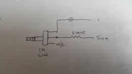
Before you test the board as a working board, do a more sophisticated test of each LDR -- connect each to 5 volts with a 300 ohm resistor plus a 1K~10K pot all in series with the LED. Sweep the pot and watch the resistance of the LDR -- should go from low resistance to very high resistance. If it doesn't do that, you have a problem LDR.
The main thing I would need to see is the LDR board removed from the other equipment and operated in isolation with a known good source and good amplifier/speaker.
I think you're saying the other channel is changing volume -- getting louder -- uncommanded, but I cannot tell if it changes volume over a few minutes or over time as you trouble shoot your board.
One concern I have is, is the entire amplifier wired correctly, and is the LDR board wired properly into the amplifier, and is something external to the LDR board causing these problems?
I feel you need to work with the LDR board entirely isolated from the rest of your setup. I suggest you remove it from your amplifier, disconnecting it from everything.
Set it up on your workbench with a regulated 12VDC supply, connect a 10K linear pot to the volume control input and a 10K linear pot to the balance control input, and wire up a source like a CD player to the input and a known working amplifier & speakers to the output (a cheap powered computer speaker system would work well).
Determine the location of the bad LDR so you know what to expect, and recalibrate the board and determine if the board works as you would expect it to with one bad LDR -- one channel stays low, the other channel functions normally.
If it does work properly, the one channel is OK, if not, then perhaps that original over-voltage created more badf LDRs or other damage to the board. Does the 5V regulator maintain a very precise 5 volts for extended periods being on? Do you have a way to measure total board current draw? Should be no more than 100ma during calibration and no more than 50ma during operation.
In other words, the usual basic troubleshooting rules appy -- simplify the circuit, then test basic properties like power supply stability, then narrow the problem to a single channel if possible, then test the components in that channel.
Before you test the board as a working board, do a more sophisticated test of each LDR -- connect each to 5 volts with a 300 ohm resistor plus a 1K~10K pot all in series with the LED. Sweep the pot and watch the resistance of the LDR -- should go from low resistance to very high resistance. If it doesn't do that, you have a problem LDR.
The main thing I would need to see is the LDR board removed from the other equipment and operated in isolation with a known good source and good amplifier/speaker.
Ok Karl, I will order a couple of pots, this will take a few days before I can test. To be clear, I have one loud channel, the volume cannot be changed regardless of time but the display does show volume movement. The other channel is quiet, this is obviously the bad shunt, this volume does not change uncommanded or over time, I can get it to go louder when the display gets to 90 something, so only the last 10 digits produce any change. This can be repeated if I swap the bad shunt to the other channel, everything is the same but reversed, this is regardless of other ldr positions, I've tried swapping every one, it's the same result, one loud channel that can't be controlled regardless of encoder position. Hope this gives some clue, I will order the pots and remove the board from the amp.
Ok Karl, I will order a couple of pots, this will take a few days before I can test. To be clear, I have one loud channel, the volume cannot be changed regardless of time but the display does show volume movement. The other channel is quiet, this is obviously the bad shunt, this volume does not change uncommanded or over time, I can get it to go louder when the display gets to 90 something, so only the last 10 digits produce any change. This can be repeated if I swap the bad shunt to the other channel, everything is the same but reversed, this is regardless of other ldr positions, I've tried swapping every one, it's the same result, one loud channel that can't be controlled regardless of encoder position. Hope this gives some clue, I will order the pots and remove the board from the amp.
It sounds like the one loud channel is wide-open. That could be caused by the shunt LDR damaged and stuck in high resistance, or a drive circuitry problem not delivering current to the shunt LDR. If the loud channel cannot be controlled regardless of volume position and even after moving the LDRs around, then I would guess a drive circuit problem or -- more likely because the drive circuitry is pretty robust -- there is a chip leg that got curled under instead of going in the socket hole and the control chip commands are not reaching the drive circuit. Please gently pry out the chip far enough to see the pins and look for a bent one folded under the chip instead of in the socket.
The quiet channel gets a little louder when the series LDR reaches very low resistance, and that only happens at the end of volume control travel.
For the next two weeks my ability to respond will be limited as we are in the final stages of packing up our house and moving to a new one. For now, please look at the chip insertion, check the LDRs as I've described earlier and, finally, test the board outside of the amplifier. I'll get back to you as I am able, but no guarantees for a while, sorry, it's bad timing.
Thanks Karl and absolutely no probs, I'm not in a rush, I've had 4 days off work which is why I was able to post, back tomorrow and I have a 3118 amp that ive done quite a bit of modding doing the work for now, to be honest the little amp with a laptop power supply very likely to replace this beast, I will be keeping the LDR though so as and when, no drama. For the record I think it's 2 bad shunts because the fault switches channel when I switch the shunts, will the circuit work with only 2 LDRs? I will order the pots anyway.
Good luck with the move.....
Good luck with the move.....
wapo - have you done any direct sound quality comparisons of your LDR volume control vs a highest quality switched attenuator (i.e. Vishay foil fixed series and switched parallel resistors, hard silver rotary switch)? I am sceptical that an LDR could match that, or even a cheaper version with switched parallel film resistors like Welwyns.
I have not made such a comparison, I have no idea how it might stack up.
Many people are skeptical of LDR sound quality until they hear it, I certainly was. I've read threads that contained fierce arguments about the sound of LDRs with strong opinions on both sides. Typically, people who have heard them are proponents and their opponents are people who have not listened to them and are skeptical because LDRs do not "measure" well. I don't think I've ever heard of anyone who was not impressed after listening to them, though they may be out there.
When I started working on this project I did it for the challenge of creating a digitally-controlled LDR attenuator. not because I loved the sound -- I'd never heard them at that point. But when I finally put a working design into my own audio system, I was stunned by the improvement in the sound and I was sold.
The much more expensive Tortugua LDR system has been tested against several other high-end alternatives. Google it.
From www.6moons.com:
The realization of no mechanical contact on either volume pot or input selector appears to succeed at contributing less and revealing more. The Tortuga Audio preamp equalled or surpassed all basic performance parameters against any contenders I had in house, passive, active, tube, FET and at any price level with regards to faithfulness.
http://www.6moons.com/audioreviews/tortuga/4.html
I think that the LDR-attenuator from BTF is based on the same principles, but with a different set of features. The LDR based attenuators come out at the very top of all the tests I have read.
Wapos‘s stuff looks very interesting.")
From www.6moons.com:
The realization of no mechanical contact on either volume pot or input selector appears to succeed at contributing less and revealing more. The Tortuga Audio preamp equalled or surpassed all basic performance parameters against any contenders I had in house, passive, active, tube, FET and at any price level with regards to faithfulness.
http://www.6moons.com/audioreviews/tortuga/4.html
I think that the LDR-attenuator from BTF is based on the same principles, but with a different set of features. The LDR based attenuators come out at the very top of all the tests I have read.
Wapos‘s stuff looks very interesting.
Last edited:
The pots have landed so heres the results for just the ldrs, not sure if i should of connected the third leg on the pot but the resistance didnt go very high on any. 3 of them went from their lowest value (which ive already stated) to 270-350 ohms, the dodgy one only went up to 100 ohms but it stays around 200 when powered down. I havnt checked the board yet....
Attachments
The pots have landed so heres the results for just the ldrs, not sure if i should of connected the third leg on the pot but the resistance didnt go very high on any. 3 of them went from their lowest value (which ive already stated) to 270-350 ohms, the dodgy one only went up to 100 ohms but it stays around 200 when powered down. I havnt checked the board yet....
Basic criteria for good LDR:
1. At 10ma, the LDR reads < 40 ohms (red dot) < 60 ohms (non red dot).
2. As current is varied (move the pot) the resistance changes appropriately and smoothly.
3. With power completely removed, the resistance is > 1 megohm.
If an LDR meets all of those standards, it's almost certainly good. If not, you should replace it.
Thanks Karl. Then if the resistance values i show are ok it looks like i still have just one bad ldr as it doesnt go high with power off. i will check the board over the weekend, its out and ready but im off to catch ELO at the O2....
Hello,
I would be interested to purchase the BTF systems LDR kit but would like to first clear some details that are only of personal concern with respect with my specific order. In this sense, is the contact form on the BTFsystems.com site operational, or must any form and coomunication content run over this site here? I am asking because I sent some questions over the BTFsystems site some weeks ago, unfortunately with no response.
Many thanks in advance for an info or hint.
Best regards,
Adrian
Alan,
This morning (Monday U.S.) I sent you an airmail envelope with a complete set of new LDRs and two freshly updated ICs required for your rotary encoder / infrared controller board. You should have them in plenty of time for that 15 July date unless something goes seriously wrong in the mail.
We are still struggling through this move but at least I can find a few things now!
Please let me know when you've received the parts and how they are playing.
Hello,
I would be interested to purchase the BTF systems LDR kit but would like to first clear some details that are only of personal concern with respect with my specific order. In this sense, is the contact form on the BTFsystems.com site operational, or must any form and coomunication content run over this site here? I am asking because I sent some questions over the BTFsystems site some weeks ago, unfortunately with no response.
Many thanks in advance for an info or hint.
Best regards,
Adrian
Adrian, I have been in the process of moving houses and things have been quite upset. However, I should have received your earlier email; if you would like to communicate, please send another email to webquery@btfsystems.com and I will receive it.
Thanks.
Alan,
This morning (Monday U.S.) I sent you an airmail envelope with a complete set of new LDRs and two freshly updated ICs required for your rotary encoder / infrared controller board. You should have them in plenty of time for that 15 July date unless something goes seriously wrong in the mail.
We are still struggling through this move but at least I can find a few things now!
Please let me know when you've received the parts and how they are playing.
Thats great news thanks Karl, I just got your email last night as i was hitting the sack. Will ping that cost over when I get the packet as per your instruction. I think the lack of notifications may be due to reading responses in our email client and not clicking the link to visit the site, the email says no more notifications until you visit the thread, strange though because ive looked at my email history and i replied to post 131 which was my last notification, maybe the site is miss behaving.
Just a quick update, chips and LDR's in, fully functioning on the bench, next step try to get it to work in my amp!
Many thanks for getting those bits out Karl, cant wait to finally get this set up.
Good luck with that, hope it goes smoothly this time!
Its ALIVE!
Its all working as expected I think, I say i think because i dont know how quiet the volume should be when its at number one, its showing 4.2 both sides, I haven't hooked up my plate amps yet so im not sure if this is going to be a bit too loud for late nights, to be honest im not that worried as I dont really listen late anyway. Should it be super quiet on number one? The only time this could be an issue is if i have a source with more gain or change the amps for higher gain?
Anyway, I had to shorten the I2c cable, it was giving unpredictable readings on the display, I.E. the no data reading, its perfect now. Also thought it was worth a mention that my final ground scheme is different to the published schematic and it is absolutely silent, the pic i posted in #111 where i have linked the left and right grounds together on the ldr board and on my chassis works a treat. I have only done this because the DCB1 has one ground connection not 2.
Now i just need to finish the front plate on the case.
Its ALIVE!
Its all working as expected I think, I say i think because i dont know how quiet the volume should be when its at number one, its showing 4.2 both sides, I haven't hooked up my plate amps yet so im not sure if this is going to be a bit too loud for late nights, to be honest im not that worried as I dont really listen late anyway. Should it be super quiet on number one? The only time this could be an issue is if i have a source with more gain or change the amps for higher gain?
The 4.2 on both sides at volume level "1" means that in your particular system no LDR will ever draw more than 4.2 milliamps during playback, and that only at minimum volume, 48.5 dB attenuation. In mute, it actually draws much less than that and you can leave it muted forever without any concern for LDR damage. In the middle range of the volume control where I expect most of your listening will occur, the LDRs typically draw less than one milliamp each and often less than one-tenth of a milliamp. You can see on the display that a lot of the volume level happens at vanishingly small amounts of current.
The 10K LDR system with a minimum of 40 ohms on the shunt during play (not mute) will give you 48.5 dB of attenuation. It's conceivable if you have a very high gain system that it won't be enough. However, you have replaced the preamp with the LDR and that removes a fair amount of potential gain. I myself have never had a problem.
I cannot turn my system down to just barely audible, but I can turn it down until it is playing very very softly. I think you will be pleased with the attenuation and it won't be a problem at all.
When you start to listen, if you have any mismatch of levels between channels I would invite you to recalibrate your LDR board now that your RE/IR board is working and you can monitor the calibration progress on the OLED display.
Anyway, I had to shorten the I2c cable, it was giving unpredictable readings on the display, I.E. the no data reading, its perfect now. Also thought it was worth a mention that my final ground scheme is different to the published schematic and it is absolutely silent, the pic i posted in #111 where i have linked the left and right grounds together on the ldr board and on my chassis works a treat. I have only done this because the DCB1 has one ground connection not 2.
Now i just need to finish the front plate on the case.
The permissible control cable length between the RE/IR board and the LDR board is somewhat dependent on how electrically noisy the environment is as well as the nature of the cable. You have a lot of stuff tightly fitted into that one box, I'm not surprised that you need to keep the control wiring fairly short. You could use shielded cable or twist each control wire with a wire grounded at one end if you need more distance.
If the two grounds are connected together at the DCB1 board, I doubt if it makes much difference that they're also connected at the LDR board. However, I also think that it wasn't necessary to connect them; my intent in keeping them separate at the LDR board was to treat each audio cable as a separate entity with a simple series-shunt resistance to attenuate the signal. This allows the source and the load to do anything they want with the grounds.
By connecting the two grounds together at the LDR board you have taken control of that away from the source and load electronics, and the grounds will always be connected together regardless of how the source and load devices are wired. There's probably no harm in that, just remember what you've done so that if ever there is a change (such as removing the DCB1 from the circuit), you'll know where they're still connected together at the LDR board.
Last edited:
- Status
- This old topic is closed. If you want to reopen this topic, contact a moderator using the "Report Post" button.
- Home
- Vendor's Bazaar
- BTFSystems precisionLDR modules for digitally-controlled LDR Passive Preamp