Dawg, the grounding as drawn in your diagram is wrong. Go back to the schematic as published on my website, and follow it exactly. All will then be well.
Any chance you could elaborate a little please? if all my pics are wrong i dont see how i can implement the LDR with the DCB1 only having one common ground, i have indeed gone back to the published schematic many many times and my third pic is as far as i can tell as close as i can get with the buffer only having one ground point.
Here is the published schematic which is as far as i can see exactly how I have drawn it in my third pic, and this is wrong? Could you please tell me what is the correct way to wire it because i can look at this all day but its not going to help. 
Attachments
Last edited:
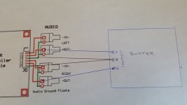
If the 'setup' on photo 1 on post #100 works okay with your system, when you replace the pot (with it's common ground connections) with the ldr volume control, all you have to do is connect the single ground wire from the phono plugs to both of the 2 GND points on the input/output terminal board (connect the Rt GND & Lt GND with single wire) and then continue just the single ground wire to the input GND point of the dcB1
This way, you've unsoldered the volume pot and connected the ldr pcb with the very same wires - no parallel connections, no links, or anything - and if it worked with the pot, there's no reason at all that it won't work with the ldrs
As you can see from the diagram, the LDR volume unit has 2 completely separate signal and ground wire connections - it's as if you had just cut the LDR volume control into your separate Right and Left interconnects - note the separate ground connection bit
What you've done is to common up these separate ground/shield wires at the input of the dcB1, and this is where some of the problems come from ...
If your dcB1 common ground point is connected to the mains earth pin via the Salas shunt reg board, this is your signal ground point for the whole system and all other earth connections have to be 'lifted' to avoid earth loops - in preamps, tuners, dacs etc, this is usually done by separating the chassis earth and the central ground point of each device,
If the 'setup' on photo 1 on post #100 works okay with your system, when you replace the pot (with it's common ground connections) with the ldr volume control, all you have to do is connect the single ground wire from the phono plugs to both of the 2 GND points on the input/output terminal board (connect the Rt GND & Lt GND with single wire) and then continue just the single ground wire to the input GND point of the dcB1
This way, you've unsoldered the volume pot and connected the ldr pcb with the very same wires - no parallel connections, no links, or anything - and if it worked with the pot, there's no reason at all that it won't work with the ldrs
As you can see from the diagram, the LDR volume unit has 2 completely separate signal and ground wire connections - it's as if you had just cut the LDR volume control into your separate Right and Left interconnects - note the separate ground connection bit
What you've done is to common up these separate ground/shield wires at the input of the dcB1, and this is where some of the problems come from ...
If your dcB1 common ground point is connected to the mains earth pin via the Salas shunt reg board, this is your signal ground point for the whole system and all other earth connections have to be 'lifted' to avoid earth loops - in preamps, tuners, dacs etc, this is usually done by separating the chassis earth and the central ground point of each device,
Many thanks james, Im going to read this a few times! I dont think i have connected the buffer to the chassis, i wanted to do the diode thing but havnt got round to it yet. I will see if i connected mains earth to my returns, I dont think so.... as far as i remember only the Audiosector amps had a chassis connection on them.
If the 'setup' on photo 1 on post #100 works okay with your system, when you replace the pot (with it's common ground connections) with the ldr volume control, all you have to do is connect the single ground wire from the phono plugs to both of the 2 GND points on the input/output terminal board (connect the Rt GND & Lt GND with single wire) and then continue just the single ground wire to the input GND point of the dcB1
This way, you've unsoldered the volume pot and connected the ldr pcb with the very same wires - no parallel connections, no links, or anything - and if it worked with the pot, there's no reason at all that it won't work with the ldrs
As you can see from the diagram, the LDR volume unit has 2 completely separate signal and ground wire connections - it's as if you had just cut the LDR volume control into your separate Right and Left interconnects - note the separate ground connection bit
What you've done is to common up these separate ground/shield wires at the input of the dcB1, and this is where some of the problems come from ...
If your dcB1 common ground point is connected to the mains earth pin via the Salas shunt reg board, this is your signal ground point for the whole system and all other earth connections have to be 'lifted' to avoid earth loops - in preamps, tuners, dacs etc, this is usually done by separating the chassis earth and the central ground point of each device,
(connect the Rt GND & Lt GND with single wire)
no parallel connections, no links, or anything
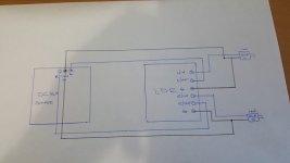
Apologies if this is a stupid question but how do i connect the 2 ground points on the LDR board with a single wire and not have any links? do you mean a single wire to each point as in pic No 4? (attached)
After metering the build it appears the 3178s CHG connection is part of the return path so I have an earth connection on the 2 amps but nowhere else, I have not yet wired the buffers shunt connection to the chassis but when i do it will float via diodes as per recomendation. It does work just fine as is but the LDR needs a floating audio ground so do you think I should remove the chassis connection on peters amps? Or should I be doing the diode thing on the 3175s too so the signal is totally earth free? I should of included that on my original schematic.
Thanks again for the help James, i didnt realise I can only have one earth connection in the entire system, I bet my av amp has an earth on it, seems to work ok when use the new build as my front channels though. I think I need to order some diodes.
Attachments
James is the expert in this area, I defer to him, but the ground system as drawn in photo one makes me wonder if there is a common point where all of the signal grounds are connected to each other just once?
Are you familiar with the "star" ground system? If you have more than one ground connection between components this may be causing a problem. For example, the LDR ground is connected to the buffer and the amplifier ground, but you also have the amplifier ground separately connected to the buffer and that creates a ground loop.
Also, if you previously reversed inputs and output somewhere that's not a ground issue, did make sure you didn't do it again? "Massive" buzzing could be a feedback loop rather than a ground loop.
Yeah, sorry about that extra link bit - just connect the 2 GND points on the ldr's input/output terminals with an extra short bit of wire between the terminals - no long wire from the phono plugs or anything - and use the one ground wire as per the previous pot method - keep it as similar to the way you had the pot connected as you know that way worked okay -
It may not be the way that I would do it but there are quite a few different methods about doing 'ground' connections.
You have to be a bit circumspect about 'willy nilly' floating earth and ground connections - there's the usual problem of having 2 grounds connected via 2 separate pieces of gear and their power supplies and earth pins on power points, etc - years ago we used to often get around this by simple cutting off the earth pins of the mains plug, stupid as it seems - dunno why we didn't electrocute ourselves actually!
On the other hand, if you 'float' everything above the earth/ground point in all the gear, or individual circuits, you get the problem of 'floating shield wires' and no protection against spurious hum and noise
As you system works with the way you wired up the pot, I'd simply do the same arrangement with the ldr Vol control - keep it as familiar/simple until you get it sorted out - can get a bit more adventurous later on
Personally, I'd leave the amps alone as they're functioning okay - you could float the central 0 volt point above the chassis ground via a 10R resistor, thermistor (see the First Watt amplifier method), etc, without much problems but make sure any of the input phono socket grounds are connected to the central 0 volt point and not to the chassis as this will create problems.
It's a bit hard to be precise as ground connections are hard to describe accurately and we take lots of details for granted
As for floating the dcB1, I normally 'float' the central '0 volt' point of preamps, buffers, etc above the chassis ground with a 100R resistor and/or diode, capacitor system - 100R thermistors work pretty well also.
All the best and hope this helps ....
Yeah, sorry about that extra link bit - just connect the 2 GND points on the ldr's input/output terminals with an extra short bit of wire between the terminals - no long wire from the phono plugs or anything - and use the one ground wire as per the previous pot method - keep it as similar to the way you had the pot connected as you know that way worked okay -
It may not be the way that I would do it but there are quite a few different methods about doing 'ground' connections.
You have to be a bit circumspect about 'willy nilly' floating earth and ground connections - there's the usual problem of having 2 grounds connected via 2 separate pieces of gear and their power supplies and earth pins on power points, etc - years ago we used to often get around this by simple cutting off the earth pins of the mains plug, stupid as it seems - dunno why we didn't electrocute ourselves actually!
On the other hand, if you 'float' everything above the earth/ground point in all the gear, or individual circuits, you get the problem of 'floating shield wires' and no protection against spurious hum and noise
As you system works with the way you wired up the pot, I'd simply do the same arrangement with the ldr Vol control - keep it as familiar/simple until you get it sorted out - can get a bit more adventurous later on
Personally, I'd leave the amps alone as they're functioning okay - you could float the central 0 volt point above the chassis ground via a 10R resistor, thermistor (see the First Watt amplifier method), etc, without much problems but make sure any of the input phono socket grounds are connected to the central 0 volt point and not to the chassis as this will create problems.
It's a bit hard to be precise as ground connections are hard to describe accurately and we take lots of details for granted
As for floating the dcB1, I normally 'float' the central '0 volt' point of preamps, buffers, etc above the chassis ground with a 100R resistor and/or diode, capacitor system - 100R thermistors work pretty well also.
All the best and hope this helps ....
Its all going in the memory bank and its now here when that fails which it seems to be doing quite a lot lately. Thanks James.
James is the expert in this area, I defer to him, but the ground system as drawn in photo one makes me wonder if there is a common point where all of the signal grounds are connected to each other just once?
Are you familiar with the "star" ground system? If you have more than one ground connection between components this may be causing a problem. For example, the LDR ground is connected to the buffer and the amplifier ground, but you also have the amplifier ground separately connected to the buffer and that creates a ground loop.
Also, if you previously reversed inputs and output somewhere that's not a ground issue, did make sure you didn't do it again? "Massive" buzzing could be a feedback loop rather than a ground loop.
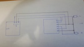
Cheers Karl, I definitely connected it up the right way round as i made some new links for the inputs, As james says i may re visit the chassis connection but i do only have one ground connection which i left off the pic, ive attached the full schematic, there is always the possibility of the input output board been damaged by my previous mistake, i will go a little slower this time....
Attachments
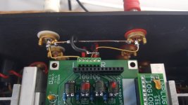
On your photo above, what's the line between the 'L' and 'R' amps connected to the CHG labels? Are they CHassis Ground connections?
The diagram of the volume pot is quite misleading - I presume this is just the way it's connected?
Sorry Karl, cross posted, but we both seem focusing on possible earth loops, my favourite nightmares!!
I think that AndrewT is an expert in this area - I've finally learned how to avoid most of these problems but ....
On your photo above, what's the line between the 'L' and 'R' amps connected to the CHG labels? Are they CHassis Ground connections?
The diagram of the volume pot is quite misleading - I presume this is just the way it's connected?
Sorry Karl, cross posted, but we both seem focusing on possible earth loops, my favourite nightmares!!
I think that AndrewT is an expert in this area - I've finally learned how to avoid most of these problems but ....
Yes thats the chassis ground connection, I made a mistake with the pot, i had been drinking all day when i started drawing, never a good time to solder but essentially yes the ground connection on the pot should be at one end not in the middle but i guess i could of said its just that brand of pot but i like to show what an idiot i am, lol.
Well its finally working, sort of, need some diagnostics from Karl. Its still on my bench so i need to do some measuring with some help with what to measure, the amp is now quiet so thanks James, i put a link between the 2 ground points on the LDR and connected the joined rca's and the dcb1 to that link.
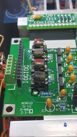
Now its playing music but one channel is substantially quieter than the other, Ive checked the balance on the LDR and its in the middle, bearing in mind i recalibrated when i got the new chip and i checked all the LDRs where do i start? I did notice the white dots on the devices is at the opposite side to the white dot on the board but i guess this means nothing as one channel is perfect.
Attachments
The white dots must align with the white dot on the board. The white dots all point toward the voltage regulator side.
The red dot LDRs are inserted in the socket with "red" printed at the foot. I can see that's correct.
The balance control is a linear pot, right? Not a "volume" (log) pot?
Did you note in the description that when the balance pot is moved, the LED goes dark for about a second when the balance is moved to exactly centered? So if you move the pot and the LED goes out for a moment you know that you're at acoustic center.
Try switching the LDRs between channels. Accepting that some error in tracking will occur because the board will be out of calibration when you move the LDRs, if the quiet channel moves to the other side you'll know you might have a bad LDR. If it stays in the same channel after moving the LDRs, you have a problem elsewhere. Remember to move the LDRs back to their original positions afterwards, or recalibrate the board with the LDRs in the new locations. Keep the red dot LDRs in the red dot sockets.
If the quiet channel moves with the LDR, try recalibrating the board before assuming a bad LDR.
One thing I wondered about from a much earlier post:
Is the power amp in the same chassis as the buffer and LDR board? You had mentioned paralleling an output RCA with the amplifier and turning the amp off when using the output RCA to drive other amps. Where does the buffer fit in all of that?
I'm wondering if the shut-down amplifier's input could act as some kind of filter network to affect the sound at the RCA output? I guess it would depend on the passive components involved and the semiconductor at the amp's input. Just wondering. Nothing to do with your current issue, just a sound-quality consideration to deal with after you solve you silent channel issue.
The white dots must align with the white dot on the board. The white dots all point toward the voltage regulator side.
The red dot LDRs are inserted in the socket with "red" printed at the foot. I can see that's correct.
The balance control is a linear pot, right? Not a "volume" (log) pot?
Did you note in the description that when the balance pot is moved, the LED goes dark for about a second when the balance is moved to exactly centered? So if you move the pot and the LED goes out for a moment you know that you're at acoustic center.
Try switching the LDRs between channels. Accepting that some error in tracking will occur because the board will be out of calibration when you move the LDRs, if the quiet channel moves to the other side you'll know you might have a bad LDR. If it stays in the same channel after moving the LDRs, you have a problem elsewhere. Remember to move the LDRs back to their original positions afterwards, or recalibrate the board with the LDRs in the new locations. Keep the red dot LDRs in the red dot sockets.
If the quiet channel moves with the LDR, try recalibrating the board before assuming a bad LDR.
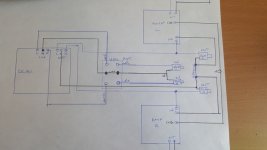
Thanks Karl, never thought of swapping the devices over, i started another calibration already so i will do that next, the white dots i refer to are at the back of the board on the pcb, theres one at each device, only the shunts have a white dot on the front of the pcb facing the regs, i guess those white dots on the pcb are not there to orient the ldrs, i left them as they where received.
Oh and i bought the full kit remember, only the rotary encoder here.
Attachments
Last edited:
One thing I wondered about from a much earlier post:
Is the power amp in the same chassis as the buffer and LDR board? You had mentioned paralleling an output RCA with the amplifier and turning the amp off when using the output RCA to drive other amps. Where does the buffer fit in all of that?
I'm wondering if the shut-down amplifier's input could act as some kind of filter network to affect the sound at the RCA output? I guess it would depend on the passive components involved and the semiconductor at the amp's input. Just wondering. Nothing to do with your current issue, just a sound-quality consideration to deal with after you solve you silent channel issue.
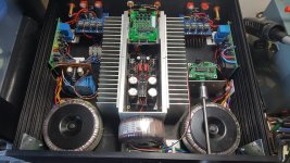
Yeah buffer, LDR, amp all in one chassis, short signal paths always for my builds. The main reason for paralleling the buffer output was so i could run my plate amps from the buffer instead of the chip amps, I couldnt get a definitive answer on the best way to run separate amps on the audiosector build thread but the designer of the buffer said there would be no issues doing it via the DCB1. I decided to wire the chip amps power via a switch so they could be turned off effectively turning the build into a passive buffered pre but my intention was always to run both sets of outputs for my bass drivers. As it happens i havnt tried my plate amps on the rca's yet because the chip amps seem to run them just fine, ive had issues with other amps doing it this way hens the backup plan. right calibration complete....
Ok ive swapped the LDRs and it didnt change so its something else, is there anything i can measure with a dmm on the ldr board?
oh i havnt swapped the shunts, thought they had to stay, just re read what you said and see they just need to stay in red dots pos.
getting somewhere now, will recal with the shunts swapped, thats the problem so looking like i do need a shunt, will let you know.
oh i havnt swapped the shunts, thought they had to stay, just re read what you said and see they just need to stay in red dots pos.
getting somewhere now, will recal with the shunts swapped, thats the problem so looking like i do need a shunt, will let you know.
Last edited:
Looks like i have to put the old pot back in, I am going to remove the ldrs and measure them all again, i dont understand whats going on, I hadnt tried the volume on the louder channel, its getting worse.
Calibration hasnt solved the problem and this is now how its working, or not...
I have one loud channel that appears to have no control of volume, i have one very quite channel that gets louder between about 95-99. If i swap the non shunt ldrs nothing changes, swapping the shunts moves the loud channel to the other side. Is it possible both shunts are damaged but in a different way? could i pop a non shunt from the quite side into the shunt pos on the loud side just to see if its just the shunts that are damaged?
Re measured all the LDR's, I used a plug in power supply this time, 5.03v unloaded. 300r.
LDR1
1.88v 10.36ma 49r
LDR2 (shunt)
1.8v 10.51ma 23r (this must of been the one i previously measured at 27r, think its faulty as its also measuring 196r at off and none of the others do this)
LDR3
1.78v 10.5ma 49r
LDR4 (shunt)
1.79v 10.5ma 39r
awaiting your confirmation but even with one faulty shunt this doesnt explain the issue I am having with both channels does it?
I will bench the unit until the fault is found, no point putting the pot back in.....
Re measured all the LDR's, I used a plug in power supply this time, 5.03v unloaded. 300r.
LDR1
1.88v 10.36ma 49r
LDR2 (shunt)
1.8v 10.51ma 23r (this must of been the one i previously measured at 27r, think its faulty as its also measuring 196r at off and none of the others do this)
LDR3
1.78v 10.5ma 49r
LDR4 (shunt)
1.79v 10.5ma 39r
awaiting your confirmation but even with one faulty shunt this doesnt explain the issue I am having with both channels does it?
I will bench the unit until the fault is found, no point putting the pot back in.....
Well, all LDRs -- series and shunt -- should go to high resistance when power is removed from the LED. If one shunt is staying at low resistance that would cause the volume level to stay low because the signal is going to ground through that low shunt resistance.
You can mix and match the LDRs in any way that you wish for testing purposes. Only, to ensure proper channel tracking at low volumes you need the red dot LDRs in the red dot sockets. At medium volume settings it doesn't matter which device is in which socket. Remember to recalibrate.
BTW, how long does it take for a calibration to complete? It should be 12~15 minutes. If much longer, then at least one of the LDRs isn't responding properly
On that LDR that stays at low resistance, please check to ensure that the leads on the LDR are not physically pushed together to cause a short that causes the fixed low resistance.
That's an elegant build you've got there -- very nice, indeed. We need to figure this out.
If one shunt LDR is staying at a low resistance level and the leads are not physically touching, that high voltage episode probably put excessive current through the device and the LDR is probably bad. And yes, you could have damaged more than one LDR and the symptoms could be different.
- Status
- This old topic is closed. If you want to reopen this topic, contact a moderator using the "Report Post" button.
- Home
- Vendor's Bazaar
- BTFSystems precisionLDR modules for digitally-controlled LDR Passive Preamp