Ok, Im affraid i need a little help!
So i need to pull the LDR's out of the sockets?
Which pins do i connect it to and what size resistor do i need to deliver or limit current to 10milliamps?
What is the Status LED?
Do I use a DMM to measure there resistance and how is this achieved?
Sorry for all the questions, I have no experience with LDR's but I would very much like to test them. The biggest problem is probably finding something that will supply 2v, will a 1.5v battery do the job? 2 to make 3v?
Read the NSL 32sr2 data sheet here: http://datasheet.octopart.com/NSL-32SR2-Silonex-datasheet-77138.pdf
The cathode (negative) side of the LED in the LDR is the side with the white dot on the body of the LDR. The wires are slightly wider apart on the LED end of the LDR, the resistor wires are closer together at the other end.
The LDR voltage drop is around 1.9~2.1 volts at 10 milliamps. If you use a 3.0 volt source like two 1.5V batteries, you need to put a resistor in series that will drop 1.0 volts at 10 milliamps (leaving 2.0 volts to drop across the LDR). Use Ohm's law to find the size of resistor required. Ideally, you'd use a resistor that's almost right for the circuit, then add a low value (100~500 ohm) variable pot in series for fine tuning. You want to put a meter in series in the circuit so you can read the current flowing through the circuit. Limit flow to no more than 20 milliamps, and 10 milliamps is your target.
With the 10 milliamps flowing, read the resistance at the other end of the LDR, it should be less than 100 ohms and more than 30 ohms.
If you have a very high resistance that means the LED side of the LDR is not producing light because it was destroyed by the high voltage that went through it.
I see from the picture that you did not have the status LED connected, so disregard that part. (It was packed with the IR sensor.)
Thanks for the instructions Karl, i will see what resistors I need then get an order at RS. I the Rotary encoder board seems to work ok, the display shows varying volume when I turn it.
I wish I had better news for you. In your picture it appears you've connected the 12V power supply to the 5VDC output terminals.
The +12V input terminals which deliver power to the input side of the on-board regulator are at the far end of the terminal strip and are marked 9~16VDC In. Look at the wiring schematic under the technical tab at BTFSystems LLC - BTFSystems LDR passive preamp, and you will see the error.
The 143.3 is what you get when the rotary encoder board is working properly but the LDR controller board is not providing it with any useful information to display.
You need to move the 12 volt supply wires off of the +/- 5V output screw terminals and connect them to the +9~16V input screw terminals on the LDR control board.
That will not solve your problem because you have been delivering 12VDC to a 5.5VDC MAX chip so it probably did not survive. Even if it appears to work, it is no longer reliable, so I will send you a new chip on Monday.
Karl
Hi Karl, did you manage to get the new chip in the post today?
Ive used an online calculator, if i use a 5v power supply which will save me buying batteries, It says 300ohms will drop it to 2v @10ma, do I need to fine tune if i am just checking if the optocoupler is working? I only ask as i have some 300r's here but i would need to order a variable pot to do the fine tuning.
Just thought I would test the resistor on a green led from my dcb1 build, I believe these where approx 2v. So I get 9.9ma and the voltage read 2.08v. Starting voltage was 5.15v. So this looks good to test the LDRs? The bit I don't understand and wanted to check, if I measure the volgage after the resistor with no led in circuit there is no difference, it still says 5.15, this should give you an idea of how much I understand about
electronics, I was expecting a 3v drop across the resistor. I just wanted to make sure it's ok to test the optocouplers with this resistor and voltage?
electronics, I was expecting a 3v drop across the resistor. I just wanted to make sure it's ok to test the optocouplers with this resistor and voltage?
Can the 10k balance pot be replaced with fixed resistors, or is it required to get exact channel matching between the LDRs systems for the two channels? My reason for asking is that if I were to retrofit it as a volume control in an existing line stage, I would rather not have to drill a hole for the balance pot on the front panel if I never use the balance control.
Second question:
If the line stage is already equipped with a 50k log ALPS motor pot, can I just replace the ALPS pot with a 10k lin ALPS pot (or similar) for the LDR system, or is the current too high over time for a normal ALPS audio pot? I am am fishing for a cheap remote solution for the LDR system here.")
Second question:
If the line stage is already equipped with a 50k log ALPS motor pot, can I just replace the ALPS pot with a 10k lin ALPS pot (or similar) for the LDR system, or is the current too high over time for a normal ALPS audio pot? I am am fishing for a cheap remote solution for the LDR system here.
Last edited:
Ive used an online calculator, if i use a 5v power supply which will save me buying batteries, It says 300ohms will drop it to 2v @10ma, do I need to fine tune if i am just checking if the optocoupler is working? I only ask as i have some 300r's here but i would need to order a variable pot to do the fine tuning.
Alan, the chip is in the mail.
Yes, a 300 ohm resistor will drop 3 volts at 10 milliamps, leaving 2 volts at 10 milliamps for the LED, and that should be fine.
The LDR is rated at 20 milliamps so you are in safe territory with the 5 volt supply and 300 ohm current limiting resistor.
Just thought I would test the resistor on a green led from my dcb1 build, I believe these where approx 2v. So I get 9.9ma and the voltage read 2.08v. Starting voltage was 5.15v. So this looks good to test the LDRs? The bit I don't understand and wanted to check, if I measure the volgage after the resistor with no led in circuit there is no difference, it still says 5.15, this should give you an idea of how much I understand about
electronics, I was expecting a 3v drop across the resistor. I just wanted to make sure it's ok to test the optocouplers with this resistor and voltage?
If you are sure about the current through the LDR at 20 milliamps (which you can measure using the current range of your meter (you might need to use a different connection to the meter that is dedicated to measuring current) then what you need to know is the LDR resistance when you are passing the current through the LED side.
On the LED side you must ensure you observe polarity. On the resistor end of the LDR, you can measure the resistance without regard to polarity. The resistance at 10 milliamps should be in the range of 30-to-100 ohms.
Can the 10k balance pot be replaced with fixed resistors, or is it required to get exact channel matching between the LDRs systems for the two channels? My reason for asking is that if I were to retrofit it as a volume control in an existing line stage, I would rather not have to drill a hole for the balance pot on the front panel if I never use the balance control.
Second question:
If the line stage is already equipped with a 50k log ALPS motor pot, can I just replace the ALPS pot with a 10k lin ALPS pot (or similar) for the LDR system, or is the current too high over time for a normal ALPS audio pot? I am am fishing for a cheap remote solution for the LDR system here.
First answer:
If you use the LDR board only (without the rotary encoder board), then yes you can use fixed resistors in a voltage divider to create 2.5 volts to feed the balance control input -- use two 1% resistors to create the voltage divider with the balance wiper attached to the junction of the two resistors. Total value of the resistors must be =< 10K and => 5K.
Second answer:
Not sure I understand the question, I'll just give you some information and maybe I'll be lucky. If you were to use my LDR board in an existing preamplifier, it is the LDRs that replace the existing pot, not the 10K linear pot specified for control. The 10K linear pot ONLY sets the control voltage delivered to the board to tell it where in the 48.5dB range to set the LDRs, and no signal passes through the 10K linear pot. The signal passes through ONLY the LDRs located on the board.
The LDRs on my board are set to emulate a 10K pot. If your preamp is OK with a 10K pot versus the existing 50K pot, you're good to go. If you want a 50K LDR pot to exactly duplicate the existing 50K alps pot, you would have to change the resistors on the calibration jumper to a different value. You can change the value so that the LDRs will be calibrated to emulate a 50K pot instead of a 10K pot. This is theoretically easy to do, but I have not tried it. You would still have a 48.5dB attenuation range because the low resistance calibration would change in tandem with the high resistance, and the ratios would remain the same.
There is very little current flowing through the 10K pot. It can be any decent quality pot, and the quality of that pot does not affect the quality of the sound because no sound goes through the pot.
Last edited:
If you are sure about the current through the LDR at 20 milliamps (which you can measure using the current range of your meter (you might need to use a different connection to the meter that is dedicated to measuring current) then what you need to know is the LDR resistance when you are passing the current through the LED side.
On the LED side you must ensure you observe polarity. On the resistor end of the LDR, you can measure the resistance without regard to polarity. The resistance at 10 milliamps should be in the range of 30-to-100 ohms.
Thanks Karl and thanks for getting the chip out so quick! Ok I will check them tonight, I'm confident on the current, I've already tested the circuit on a green led as I said so I just need to apply it to the LDRs.
Ok I will check them tonight, I'm confident on the current, I've already tested the circuit on a green led as I said so I just need to apply it to the LDRs.
Did your LDRs check out OK?
Did your LDRs check out OK?
Hi Karl, I have just checked them, things got a bit hectic here..... 3 of them are within spec (around 40-50) but one is 27, im thinking its so close that its probably ok and its down to the voltage? Also wouldnt all of them be buggered? Theres a bigger drop than with my green LED that I tested the circuit on, im getting 1.79v on the LDRs. I guess I could dig out a switch mode 5v wall wart and re test, im currently using one of those usb charger packs with various outputs on it.
Last edited:
Hi Karl, I have just checked them, things got a bit hectic here..... 3 of them are within spec (around 40-50) but one is 27, im thinking its so close that its probably ok and its down to the voltage? Also wouldnt all of them be buggered? Theres a bigger drop than with my green LED that I tested the circuit on, im getting 1.79v on the LDRs. I guess I could dig out a switch mode 5v wall wart and re test, im currently using one of those usb charger packs with various outputs on it.
No, you're good. That 27 at 10 milliamps makes it a red-dot LDR, intended to go in the shunt position. If you're getting 27 ohms at 10 milliamps, that means at biggest draw at 40 ohms it'll probably only draw maybe 4 milliamps or less of current.
This variation is perfectly OK, actually very good. It's a low current sample, and the computer chip will calibrate it with no difficulty down to 40 ohms.
If the other three are also within spec, you'll be good to go when your chip arrives. Make sure you put the red dot LDRs back in the red dot positions.
BTW, please let me know when it does arrive.
No, you're good. That 27 at 10 milliamps makes it a red-dot LDR, intended to go in the shunt position. If you're getting 27 ohms at 10 milliamps, that means at biggest draw at 40 ohms it'll probably only draw maybe 4 milliamps or less of current.
This variation is perfectly OK, actually very good. It's a low current sample, and the computer chip will calibrate it with no difficulty down to 40 ohms.
If the other three are also within spec, you'll be good to go when your chip arrives. Make sure you put the red dot LDRs back in the red dot positions.
Music to my ears!
BTW, please let me know when it does arrive.
Will do!
The chip has landed! just swapped it over and wired up the power, it seems to be all working fine, I will probably leave the temp pot in for a while so i can get a good listen before i switch over to your LDR, trouble is i have no time at the mo.
But it looks good, the ballance is now working, took a few pushes for me to get the timing right, also when i turn the encoder the volume numbers change aswell as the LDR current readings so im taking that as all good, ive left it calibrating now then i will have to turn it all off until i can get some time.
Thank you again Karl for sending me the new chip FOC, I will report back when I get it all done, ive got a friend driving 300 miles for an ampfest in 3 weeks so thats my deadline and when it will be getting evaluated over 4 days, cant wait.
The chip has landed! just swapped it over and wired up the power, it seems to be all working fine, I will probably leave the temp pot in for a while so i can get a good listen before i switch over to your LDR, trouble is i have no time at the mo.
But it looks good, the ballance is now working, took a few pushes for me to get the timing right, also when i turn the encoder the volume numbers change aswell as the LDR current readings so im taking that as all good, ive left it calibrating now then i will have to turn it all off until i can get some time.
Thank you again Karl for sending me the new chip FOC, I will report back when I get it all done, ive got a friend driving 300 miles for an ampfest in 3 weeks so thats my deadline and when it will be getting evaluated over 4 days, cant wait.
Good news. Will you evaluate the LDR control with multiple systems, or is it hard-wired into your amplifier? Either way, I look forward to hearing the results.
Good news. Will you evaluate the LDR control with multiple systems, or is it hard-wired into your amplifier? Either way, I look forward to hearing the results.
Its hard wired but I have made it so I can bypass the chip amps, ive got a pair of RCA's hooked up to the DCB1 and I can power down the 3875's on a switch, this leaves me with an LDR DCB1 Pre amp but at the moment we only have modded 3116 amps with volume controls to compare, oh and my KT88 but they all have volume pots. Im looking forward to pulling the temp pot out though, this should be a good test as its also 10k.
Back again! So i just tried to swap my volume pot for the LDR, bit of a disaster, massive buzzing, exact same buzzing i got when i accidently swapped the input and output jacks around on the DCB1 so i think its just a ground issue. Now ive had a few beers so its getting hard for me to focus but here are my wiring options. Sorry about the pics. looks like i will have to upload and edit using the file manager......
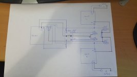
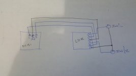
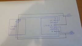
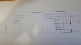
The first pic is my working circuit, dead silent so no probs, the second pic is how i implemented the LDR, I was hoping it had a common ground, should of checked really.... anyway i have one wire for my ground on the buffer so i thought it might be ok, obviouly not. Third pic is I guess how i should of done it but this involves cutting a ground/return bar between my inputs and fudging 2 cables onto the DCB1 input. After doing the drawings, is the third pic any different from the fourth? Instead of 2 wires going to the buffer i would have 2 wires going to my return/ground bar. I can see that on the BTFSystem drawing you have separated the ground on L/R inputs but with my buffer they will join together anyway?
Ive put the pot back on for now so i can relax for the evening, hopefully i will sort this tomorrow.
Attachments
Last edited:
- Status
- This old topic is closed. If you want to reopen this topic, contact a moderator using the "Report Post" button.
- Home
- Vendor's Bazaar
- BTFSystems precisionLDR modules for digitally-controlled LDR Passive Preamp