Hello: This is the first time I have participated in the forum. I want to replace the volume potentiometer with a better quality and before dismantling it would like someone to tell me the value in Omios I should buy. Thank you
100K logar.
Try the 21-step "type 21" Cheap and good.
DACT Type SMD Stepped Attenuator 21 step volume control pot D Shape Shaft | eBay
Just finished my Boyuu amplifier today. It sounds good, very little hum and a good frequency response. As there was a 220V lead supplied with this kit and i live in the UK using 240V I was cautious and added a 27 Ohm 25W resistor in series with the 39 Ohm dropper resistor after the rectifier valve. All the PSU voltages look good as does the EL34 voltages. The only voltage that is different to the schematic is the anode voltages for the 6N9P triodes. +B2 was measured as 310V. The schematic shows 150V for the anodes but I am getting 175V for the Left channel and 184V for the right channel. The coupling capacitor to the pentode grid is a 0.22uF/400V and the pentode grid resistor is 330K. I have added a 3K3 grid stop resistor to the triodes. The triode grid resistor is 150K. The triode cathode resistor is 2K and have added cathode bypass capacitors 470uF and 10nF.
Any ideas why these anode voltages are this high please???
I am also getting a slight crackling form the left channel only - It is not a connection or dry-joint sound but a constant back-of-the-box crackle. I am sure I have read somewhere that it is because of the cheap supplied Chinese valves (pre-amp valve I assume). Can anyone conform this information please?
Thanks in advance
Nigel
Last edited:
Hi NigUK
Voltage on your 6N9P valve:
I think the current in the anode resistor is a bit to small (the voltage drop on the resistor is to small). What is the voltage on the cathode? Then in my amp, the cathode resistor is 1k (and 1.5v cathode voltage), where you have 2k.
Preben
Voltage on your 6N9P valve:
I think the current in the anode resistor is a bit to small (the voltage drop on the resistor is to small). What is the voltage on the cathode? Then in my amp, the cathode resistor is 1k (and 1.5v cathode voltage), where you have 2k.
Preben
Sorry guys - just seen these replies to my post.
For the 6N9P's
The anode resistors are 100K
The cathode resistors are 2K
The voltages are as follows.
Left channel
+B2 310V
Voltage at the Anode 175V
Voltage at the Cathode 2.6V
Right channel
+B2 310V
Voltage at the anode 184V
Voltage at the Cathode 2.4V
I am however thinking of changing these valves to 6LS7's - do you think that these values and voltage differences will be a problem if I do this?
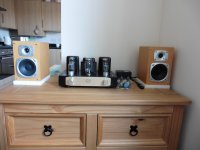
This amp is now finished and working in my lounge (pic below). This is being used with a home-built valve pre-amp kit.
Thanks
Nigel
For the 6N9P's
The anode resistors are 100K
The cathode resistors are 2K
The voltages are as follows.
Left channel
+B2 310V
Voltage at the Anode 175V
Voltage at the Cathode 2.6V
Right channel
+B2 310V
Voltage at the anode 184V
Voltage at the Cathode 2.4V
I am however thinking of changing these valves to 6LS7's - do you think that these values and voltage differences will be a problem if I do this?
This amp is now finished and working in my lounge (pic below). This is being used with a home-built valve pre-amp kit.
Thanks
Nigel
Attachments
Putting a series resistor in the B+ does not solve another potential problem (bad pun).
The filament voltages of the tubes may all be high.
240V/220V = 1.09, 9% high.
6.3V tubes are now running at 6.87V.
A series resistor in the Primary circuit would make both the B+ and Filament voltages be the same on 240V, as what the original amp voltages would have been with 220V power.
I believe you meant that you wanted to substitute a 6SL7 for a 6N9P.
You said 6LS7.
Yes my friend you are correct I meant 6SL7.
My filament voltages have been measure at 6.6V ac for both the 6N9P's and EL34's.
I can see your thinking of reducing the voltage to the all the secondaries by placing a resistor in the primary.
I assume you mean putting a series resistor in the "live" mains line before the transformer.
Do you have any suggestion of value and wattage please?
I think my main concern was the difference in anode voltages on my 6N9P's. The circuit shows I should be getting 150V for both left and right but I am getting 175V on the left and 184V on the right. Is this just because of the tollerance differences of the possibly unmatched valves?
Cheers
If you must reduce the line voltage (I would leave it alone), build a bucking transformer. You can do it with a filament transformer. Do a search on bucking transformer for vintage tube amp.
I would consider post #385 suggestion. The voltage difference you see are from tube to tube variations. Are you seeing volume (gain) difference between the two channels. If you do, try finding a matching pair and/or try post #385.
I would consider post #385 suggestion. The voltage difference you see are from tube to tube variations. Are you seeing volume (gain) difference between the two channels. If you do, try finding a matching pair and/or try post #385.
Hi Alllensoncanon,
Using a resistor in the line is a time honoured way to arrest surge currents and is quite safe to do. You just build the circuit on a PCB or tag strips just like they have done for nearly a century. Done properly it is no more dangerous than a bucking transformer.
-Chris
Using a resistor in the line is a time honoured way to arrest surge currents and is quite safe to do. You just build the circuit on a PCB or tag strips just like they have done for nearly a century. Done properly it is no more dangerous than a bucking transformer.
-Chris
A line voltage dropping resistor should rated to be able to handle at least 3 times the power ((I)squared x R) caused by the amplifier current draw.
The resistor should be in a metal enclosure (the amp or an auxiliary metal box).
There must be room for the resistor to give off its heat.
All construction should be according to electrical safety rules and regulations.
A dropping resistor example:
240V line - 220V amplifier = 20V drop required in the resistor.
Suppose the amplifier draws 0.8 Amp current.
20V/0.8 Amp = 25 Ohm dropping resistor.
(0.8 Amp) Squared x 25 Ohms = 16 Watts, use a 25 Ohm 50 Watt resistor.
This resistor either needs to be in the amplifier metal case, or a separate metal box.
In either case, the resistor should be connected After the fuse(s).
I suggest that you use 2 fuses in series:
A fast blow that is just large enough so it does not blow during the amplifier inrush current at turn-on.
A slow blow that is just large enough so that it does not blow from the current draw of the warmed up amplifier.
Safety first.
By the way, a line bucking transformer is a good idea too. It is more efficient, generates less heat than using a line dropping resistor. But it also should either be contained in the amplifier, or in a metal box.
And it must be connected After the fuse(s).
A240V to 20V transformer would work to buck 240V down to 220V (but only if connected in Buck phase, otherwise you get Boost phase and 260V!).
Last edited:
Hi 6A3sUMMER,
Power is just I*V. At any rate, your post is good and I agree with what you are saying. Some resistors will mount to the metal case and use that as a heat sink. They are rated for that differential and of course the case would be grounded just in case the insulation fails.
The resistor is small and doesn't radiate 60 Hz hum, that's why they are so popular. A bucking transformer would need to be mounted in an external box for audio equipment.
-Chris
I see a resistor that drop 10% of the voltage will also generate 10% of the heat. 10% of 100W is not a small number to deal with. In a mishap (ie. Someone working on a power line outside), that number will only go higher. It can also be a thermal run away trap if that resistant go up with age and heat. Yes I agree, if that resistor is managed properly it can be safe. Properly not a good idea on an entry level Boyuu EL34 amp.
1. anatech,
and
2. Alllensoncanon,
1. Agreed, power = I x V.
But power also = (I)squared x R
And, we want to drop 20V with a resistor that has 0.8A through it.
R = V/I
R = 20V/0.8A = 25 Ohms
And, 20V x 0.8A = 16 Watts
And, (0.8A x 0.8A) x 25 Ohms = 16 Watts, just another way of saying the same thing (same circuit).
If you want the resistor to not smoke or at least discolor, use a wattage rating of at least 3x the power it will dissipate (I usually use 5x just to make resistors run cooler; more mass and more surface area).
2. Someone whose only experience is wiring a Boyuu amp, may not be up to safely building a metal box with 2 fuses, a Buck transformer, and power lead connections and wiring; or the same parts except a resistor instead of a Buck transformer.
I only mentioned resistors and Buck transformers for those who can safely do that sort of work.
But . . . that goes for all the threads on this web.
Safety first.
IMHO, using an amplifier transformer that is made for 220VAC and powering it with 240VAC is going to make it have 10% more power loss due to the core magnetization, and up to 21% more loss due to the Isquared x R loss of the DCRs of the primary and all the secondaries. That will make the amp power transformer run hotter.
How safe is that? Depends on how much margin was engineered in.
Last edited:
Hi Alllensoncanon,
Dropping resistors on the AC line used to be quite common in industry. Pressure to make equipment efficient has curtailed that practice, same for buck transformers. Anyway. If you are going to argue safety, the bucking transformer is also out as being too dangerous for people to work with. Especially as a permanent solution. Therefore they should be forced to use a different transformer?
-Chris
We can't design for every eventuality, nor can we condemn a hobbyist as incompetent either.In a mishap (ie. Someone working on a power line outside), that number will only go higher.
No, that doesn't happen with high power resistors. The increase is measured in ppm, so thermal runaway doesn't happen in any practical form.It can also be a thermal runaway trap if that resistant go up with age and heat.
Considering the voltages that the circuits run at, I don't think the resistor is a major concern. There are so many ways a person can cause a fire or kill themselves working with anything that is AC powered that we can't single out a resistor as being a major risk. Each and every person who elects to work on things above a certain voltage level or power level is accepting a reasonable level of risk. We have clearly stated this in the notes we require members read for their own safety.Properly not a good idea on an entry level Boyuu EL34 amp.
Dropping resistors on the AC line used to be quite common in industry. Pressure to make equipment efficient has curtailed that practice, same for buck transformers. Anyway. If you are going to argue safety, the bucking transformer is also out as being too dangerous for people to work with. Especially as a permanent solution. Therefore they should be forced to use a different transformer?
-Chris
Hi, Guys ... I found this topic today for the first time ... I have question about output transformers, anybody, who knows frequency range / primary inductance ? I like to buy this kit and made some changes, who was posted here, because only separate transformers cost much more than the this whole kit ... ")
-Martin-
-Martin-
Hi Martin,
Transformers are the heart and soul of a tube amplifier. Good ones are a lot more expensive than the bargain brands.
-Chris
I know that, but I like to hear some opinion, I can buy for almost same price only transformers like Indel, and OT´s from this brand are piece of crap, for example: OT for SE EL84/6AQ5, datasheet says: 40Hz - 20000Hz, and the reality: this OT starts on 150Hz with feedback and from 300Hz without feedback ....
value for money
My opinion is based on building this amp in october 2017, since then I listen to it each day. It is very good, but it needs a sensitive woofer.
They sound Majestic on vintage 3 way speakers (currently 35watt Sansui ES-200, 1970?)
The rectifier tube was/is mechanically crap, not straight, and burnt out quickly, one EL34 was a perfect replica of the Tower of Pisa.
Bbut both tubes were replaced immediately without costs, compliments to noubsound.
After soldering in the screen-stop-resistor the amp was left where it was with this single adjustment, playing and collecting dust.
I only touch the on/off knob and enjoyed this little amp now for 10 months.
The amp is good mostly because there are no weak points, so overall it is a winner for the price. The OT's are no exception, they are not super big but need to handle effectively 5 watts at most, very loud indeed with the right speakers.
Building is much fun anyway, but if you have some experience: cut the PCB and build it "point to point". The PCB makes it all "complicated" while this is just a very simple, elegant, down to tubes amp, look at the schematic.
And because it sound beefy on good speakers it is also a very good candidate to change to triode mode or use NFB (find the topics in this thread!, remember both mods make it sound "audiophile" but at the expense of loudness. My plans to mod includes a switch "TRIODE / NFB / DISCO" to keep all variations available.
Have fun building and listening!,
Marcel
- Home
- Amplifiers
- Tubes / Valves
- Boyuu EL34 A9 Tube Amp