BOYUU A9 Valve amplifier help/suggestions
Hi All
I am new to this site. I am an electronics engineer and radio amateur trying my hand at building a valve amp.
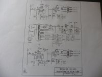
I have just bought a BOYUU A9 amplifier and have drawn some proposed modifications on the schematics (please see the attached changed schematic)
I would like some feedback on these proposals please before I build it.
For the time being I am going to use the valves that came with the unit (2 x 6N9, 2 x EL34 and 1 x GZ3P). Using 240V UK mains.
A list of these changes is as follows:
In the power supply circuit:
A 1A slow blow fuse is added in the “0” ground line of the 315-0-315 transformer tap.
C302 is changed from 150µF to a 330µF/450V
C303 is changed from 22µF to a 150µF/400V
A 200K (2 x100K 3W in series) is added in parallel with C301 (bleed resistor)
A 200K (2 x100K 3W in series) is added in parallel with C302 (bleed resistor)
A 1µF/450V is added in parallel with C301
A 1µF/450V is added in parallel with C302
A 1µF/450V is added in parallel with C303
A 47nF/450V polypropylene is added in parallel with C301
A 47nF/450V polypropylene is added in parallel with C302
A 47nF/450V polypropylene is added in parallel with C303
2 x 100Ω 3W resistors connected between each 6N9 heater to ground (hum reduction)
Chassis and audio grounds separated by a 100Ω 3W resistor with a paralleled 0.47µF/450V
A 150k 2W in series with a blue LED across C303 (a power indicator)
For Each channel
A 3K3 3W metal oxide resistor added between the pot and 6N9 g1/g2 (grid stop resistor)
R102/R202 changed from 470K to 150K (grid leak)
A 470µF/63v and 10nF added in parallel with R104/R204 (cathode bypass)
C102/C202 changed from 0.22µF to a 0.47µF (coupling)
A 10nF polyester film capacitor added in parallel with C103/C203 (cathode bypass)
The “0” tap on each output transformer disconnected from audio ground
What do you think of these modifications?
Are these value changes/additions the correct values/types?
Is there anything I propose to do unsafe?
Is there anything else you can suggest to improve the performance of this amplifier.
Also a radio amateur I have a lot of surplus RG58 50Ω coax. Can I use this instead of single core screened to connect the phono inputs to the pot and the pot to the 6N9’s?
Thank you in advance
Nigel
Hi All
I am new to this site. I am an electronics engineer and radio amateur trying my hand at building a valve amp.
I have just bought a BOYUU A9 amplifier and have drawn some proposed modifications on the schematics (please see the attached changed schematic)
I would like some feedback on these proposals please before I build it.
For the time being I am going to use the valves that came with the unit (2 x 6N9, 2 x EL34 and 1 x GZ3P). Using 240V UK mains.
A list of these changes is as follows:
In the power supply circuit:
A 1A slow blow fuse is added in the “0” ground line of the 315-0-315 transformer tap.
C302 is changed from 150µF to a 330µF/450V
C303 is changed from 22µF to a 150µF/400V
A 200K (2 x100K 3W in series) is added in parallel with C301 (bleed resistor)
A 200K (2 x100K 3W in series) is added in parallel with C302 (bleed resistor)
A 1µF/450V is added in parallel with C301
A 1µF/450V is added in parallel with C302
A 1µF/450V is added in parallel with C303
A 47nF/450V polypropylene is added in parallel with C301
A 47nF/450V polypropylene is added in parallel with C302
A 47nF/450V polypropylene is added in parallel with C303
2 x 100Ω 3W resistors connected between each 6N9 heater to ground (hum reduction)
Chassis and audio grounds separated by a 100Ω 3W resistor with a paralleled 0.47µF/450V
A 150k 2W in series with a blue LED across C303 (a power indicator)
For Each channel
A 3K3 3W metal oxide resistor added between the pot and 6N9 g1/g2 (grid stop resistor)
R102/R202 changed from 470K to 150K (grid leak)
A 470µF/63v and 10nF added in parallel with R104/R204 (cathode bypass)
C102/C202 changed from 0.22µF to a 0.47µF (coupling)
A 10nF polyester film capacitor added in parallel with C103/C203 (cathode bypass)
The “0” tap on each output transformer disconnected from audio ground
What do you think of these modifications?
Are these value changes/additions the correct values/types?
Is there anything I propose to do unsafe?
Is there anything else you can suggest to improve the performance of this amplifier.
Also a radio amateur I have a lot of surplus RG58 50Ω coax. Can I use this instead of single core screened to connect the phono inputs to the pot and the pot to the 6N9’s?
Thank you in advance
Nigel
Attachments
Do not use big power resistors for grid stoppers. There's absolutely no need for a 3W part there, a small carbon film will be fine.
Why are you changing the RC coupling values? The stock values will load the driver stage much less.
Why are you removing the ground connection to the output transformer? If there is a short between primary and secondary windings, you will really want this connection there so that the fuse in the amplifier blows. Otherwise, you're going to get shocked.
I would do absolutely none of what you propose. The biggest performance bottleneck of this amplifier will be its output transformers. Throw them away and spend $50 on something better.
The amp will also benefit from either having the output tube triode wired or having a global feedback loop added. The feedback loop should have been there from the factory, but I suspect there's so little margin for stability in this thing that it won't work without better iron.
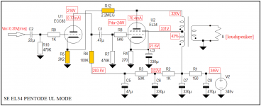
Been experimenting over the last couple of days , and have made a couple of mods that help with linerarity and power output , compared to my original . output transformers definitely are the week point and maybe the ones supplied with the ready made unit are different , they dont look the same. The windings "sing" when high level sine waves are fed through. With the resistor changes shown - 510r/470r the current draw goes up to 67mA , and the DC across the transformer goes up to around 15v , the power output now measures around 6 to 7w rms with 8R load on the 8R output. Frequency response is now good to 35Khz , and at full power to 24Khz - before it was arround 19Khz for -1db. Full o/p is with arround 800mv input signal. The .33uf 630v are there to help isolate each stage , they are Obligato premium Caps. I have made some changes at the i/p. This amp has dual i/p which i dont need , so i have used the second set as outputs and i have fitted a buffer stage at the i/p so i can feed my Bass Amp, the level control on the front becomes the level control for the buffer output, max signal handling is arround +/- 1.1v , If a bridge rectifier was used for the power , it would be considerably more.
Attachments
Hi! I have assembled this kit with same minor mods. I have a problem in the logaritmic potenziometer. I have replaced it with one of best quality but with different value: 47kohm. Well, it acts very strange. For the most of the rotation it changes very little the volume (e adds 50hz interference) then it literally jump to the maximum. I have controlled it several time when non connected and it is not damaged. I have also grounded the iron part of the potenziometer but the interference does non disappear (in that specifical range of values). Some ideas???
easygoing,
3K3 and 4k7 grid stopper resistors need to be connected directly to the grids of the tubes.
The schematic has them connected, they will not perform the job of grid stoppers.
Also, they cause a slight signal attenuation with the 470k and 330k grid leak resistors respectively.
You are using coupling caps at the input to connect to R102 and R202. Be sure not to move the coupling caps from R102 and 202. They should stay on that side of R102 and R202 when you re-connect the grid stopper resistors from the top of R102 / R202 to the grids, pins 1 and 4 (1 and 4 should be connected, not shown in the schematic).
The same goes for the 4k7 grid stoppers. Coupling cap to top of grid leak R105 and R205, grid leak to ground, 4k7 from top of R105 and 205, and other end of 4k7 to grid pin5.
Hi there.
So my experience of building this kit has gone from bad to worse (all down to my own mistakes/learning). After replacing the Power transformer, I now have all 5 valves glowing nicely through the 6.3V heaters. My problem now is that I have no sound. After checking the potentiometer/input/output circuits, I now think I may have damaged the output transformers. This theory is based on the fact that I have been foolishly powering the amp on/off without a load on the output terminal.
I've removed one of the transformers and made the following measurements on the primary circuit:
Red (+B) to Blue (line in) = 200 Ohms
Blue to Brown (+Ve on EL34) = 200 Ohms
Red to Brown = 200 Ohms
As these should be much higher, is my transformer dead? These were all measured with primary and secondary windings open.
Any help would be great. Thanks.
Grawynne,
Are Red, Blue, and Brown the primary windings of the output transformer?
If so:
Test, With all output transformer leads disconnected:
Then Short all of the secondary windings.
Then Measure the Red to Blue, Blue to Brown, and Red to Brown.
Wait for the Ohmmeter to settle in each case (takes time).
You might get 200, 200, and 400 for those measurements, not necessarily in that order.
readings even close to that are probably OK.
Reading 1 + Reading 2 = Reading 3 (again not necessarily in that order).
Output transformer primary windings may read something like 200 Ohms each, and two times that in series.
But the Impedance of the primary will be much higher than the DC Ohmmeter reading (i.e. 5k Ohms).
Thanks for the quick reply 6A3sUMMER.
Yes, these are the primary windings.
With all output windings shorted, I'm getting 100 Ohms + 100 Ohms = 200 Ohms (also measured from red to brown). So it suggests its ok, but do you think the values are too low?
Thanks for your patience")
Yes, these are the primary windings.
With all output windings shorted, I'm getting 100 Ohms + 100 Ohms = 200 Ohms (also measured from red to brown). So it suggests its ok, but do you think the values are too low?
Thanks for your patience
Really useful! ThanksThe schematic in my post # 316 is not good to see or read, so i made a redrawing.
You have to measure the Impedance at an Audio frequency, i.e. 1 kHz. It is not the same as the DC resistance.
You can make an Impedance measurement with a 50 Ohm output oscillator, a series resistor (in series with the oscillator output to the primary), that resistor value to equal the expected impedance of the transformer (i.e. 5k, or 3.5k Ohms, etc.); a voltmeter meter that can measure at 1kHz; and an 8 Ohm load resistor on the secondary 8 ohm tap.
If the voltage across the 5k Ohm resistor is the same as the voltage across the transformer primary (and with the secondary loaded, i.e. 8 Ohm resistor across the 8 Ohm tap), then the primary impedance is 5k Ohms).
Using a 10k potentiometer, you can vary it until the voltage across the potentiometer equals the voltage across the primary. Then disconnect the potentiometer (without turning the shaft again), and measure the DC resistance. That DC value is also the impedance of the primary.
Now that you have the output transformer disconnected, you can measure the primary impedance this easier way.
If you use a 50 Ohm or 600 Ohm generator, you can connect it directly to the primary (with the secondary leads open, no load), and
then connect one scope lead across the whole primary and measure the voltage.
(primary B+ lead to primary plate lead).
Then with the secondary open (no load), connect the other scope lead across the secondary, 8 Ohm tap to ground tap and measure the voltage.
Primary Voltage/Secondary Voltage = Turns Ratio.
(Turns Ratio) Squared x 8 Ohms = primary impedance.
i.e. 5V on primary, 200 milli Volts on secondary. 5/0.2 = 25 (Turns Ratio)
(25) Squared x 8 Ohms = (625) x 8 = 5000 Ohms Primary Impedance.
Likewise, with a measured Turns Ratio of 20, the Primary Impedance calculates to be 3200 Ohms.
5V/250milli Volts = 20; 20 Squared = 400; 400 x 8 = 3200 Ohm primary.
If you get primary impedances that are close to these values, you have a working transformer.
Hi I'm a newbie here and joined so that I could see the photos and diagrams in this thread. I've only read the first few pages yet so I'll come back to it once I've got it built and running and have observations to make. With your valuable guidance I am now well on the way with constructing one of these little gems.
I was very perplexed when they didn't even come with the basics like a colour code for the transformer cables so thanks to all the contributors who have saved a lot of head scratching.
I was very perplexed when they didn't even come with the basics like a colour code for the transformer cables so thanks to all the contributors who have saved a lot of head scratching.
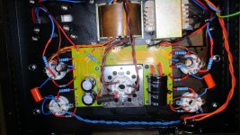
First departure from standard: I've put pins on the PCB at all the points where connections are made. I think this will be stronger (more reliable) than just soldering cables to the solder-pads.
An externally hosted image should be here but it was not working when we last tested it.
An externally hosted image should be here but it was not working when we last tested it.

Try attaching your pictures directly to the forum
How to attach your images:
How to attach images to your posts.
Thanks for the picture guidance Mooly.
I've got it just about finished- just got to fix the mains socket in place and connect the inputs then I can test it tomorrow night.
I'm doing away with the volume control pot and having a direct single input- I'll pop some resistors in to load the input in place of the pot.
Fingers crossed.
I've got it just about finished- just got to fix the mains socket in place and connect the inputs then I can test it tomorrow night.
I'm doing away with the volume control pot and having a direct single input- I'll pop some resistors in to load the input in place of the pot.
Fingers crossed.
Attachments
Well I tested it last night...
The sound was quite faint but sounded very over-driven. I think it might be a rectification problem- when I switched on the rectifier valve looked like a sparkler (hand-held firework) was burning inside just for a second or two and then it settled down...
Checking everything today.
The sound was quite faint but sounded very over-driven. I think it might be a rectification problem- when I switched on the rectifier valve looked like a sparkler (hand-held firework) was burning inside just for a second or two and then it settled down...
Checking everything today.
- Home
- Amplifiers
- Tubes / Valves
- Boyuu EL34 A9 Tube Amp