When having a better look at my solder I see it is not 60/40, but 60 Sn/38 Pb/2 Cu. So 38% lead and 2% copper. With this solder I have no problems at all.60/40 is not electronic component solder.
It is a pasty solder, i.e. it does not have a melting point.
60/40 has a melting range and while the solder is in that temperature range it becomes pasty. If disturbed during this pasty phase, the joint does not "make" properly. It will lack electrical bonding and it will lack strength.
63/37 is the eutectic solder used for electronic components.
Eutectics and there are many of them do have a melting point. They do not have a pasty phase.
Stannol solder
Datasheet It's German, you probably can't read it.
EDIT: The datasheet is outdated. It's 60 Sn/39 Pb/1 Cu
Well German is not my natal language, but I can read and speak it. It says that the alloy becomes a liquid at 183ºCCorpius.
I can't read German either. I tried looking for a word similar to eutectic, but no luck.
I see a single temperature of 183ºC stated for melting, this may indicate eutectic.
I suspect this to be a "savbit" type of solder to reduce copper erosion during soldering.
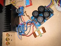
Today I hooked up my amps. First only the psb. It measured 31Vdc (positive to gnd) and -31Vdc (Negative to gnd). This was alright. then I hooked up the amps. Made sure all connections where done the right way. When measuring dc on the outputs of BOTH amps I measured 31 Vdc (output to gnd). This can't be alright! Absolutely no clue on what I did wrong here. I thought that I installed the Thiele network correctly (image). I did not connect any source or what so ever to it. could this be the problem?
Attachments
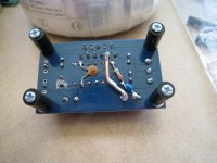
Both plus and minus power inputs connect to the right pins of the LM3886. There is no connection between both plus and minus inputs to pin 3 (speaker output). There is no excessive solder on the board that shorts some connections. Ground connects to pin 7 as supposed to be. Pin 3 to pin 9 with 22K resistance, also right. Pin 8 to pin 4 with a 22k resistor in between. No still don't get it.
Correction: It measures -31.8 Vdc (speaker output to gnd) on both amps. The power inputs measure +33.8 Vdc (positive to gnd) and -33.8 Vdc (Negative to gnd).
Correction: It measures -31.8 Vdc (speaker output to gnd) on both amps. The power inputs measure +33.8 Vdc (positive to gnd) and -33.8 Vdc (Negative to gnd).
Last edited:
Hi Guys:
I'm sorry I haven't been able to post lately, I've been very busy trying to keep my head out of the water...
Pemo, where did you find that board?. Where is it being sold?.
As you all know, I am far from being an expert in this matter, but when you mention a filter in the input, are you referring to the C7 of this new board?. If that is the case, our XY boards have that same capacitor called C5.
I think you are right about the RC network, R1 and C5 in this new board. I also see two additional capacitors, C3 and C4, obviously film type, located right next to C1 and C2, which are the same C1 and C2 caps in our XY boards but ours lack these two extra film caps. Their function is a question to AndrewT and Pacificblue. All I can say is that they look like those small film caps in front of the big electrolytics in the PSU.
I also see that the grounds seem to be properly separated, there is no need to "cut any trace bridges" on these, at least I think so, but the experts have the last word on this too.
Anyhow, it looks very interesting, the only thing I don't like is the location of the input filter cap, there is no room to place a large axial polypropylene capacitor in there, I guess it would have to be a Wima or something of that sort, other than that these looks like a much better board than the XY. Pemo, thank you for sharing. Could you please post the link to the seller of these boards?.
I found the board on eBay. Item number: 220993780260
Andrew mentioned that these boards still needs some modifications. Do you know which?
RGDS
PEMO
I'm slowly working on mine still. I went ahead and got the remote volume and input selector kit for it. I ditched the old heat sinks in favor of a pair from heatsinksusa.com. I am currently awaiting a pair of UV meters from hong Kong ( they are in New York at the moment)
This build has all but stopped at the moment as I'm still adjusting to my newborn and searching for a new home at the same time. I've also been traveling around the Midwest a lot for training. I will get this up and running eventually. until then I'm still following and learning. Good luck for the rest of your build!
This build has all but stopped at the moment as I'm still adjusting to my newborn and searching for a new home at the same time. I've also been traveling around the Midwest a lot for training. I will get this up and running eventually. until then I'm still following and learning. Good luck for the rest of your build!
Corpius:
You shouldn't have ANY DC in the output, and that voltage you measured is crazy, I just measured mine and I get 0.003 V AC on each OUTPUT to GROUND, and the same on each INPUT to GROUND. If you connect speakers, you will fry them.
Unfortunately, I can't tell you what's wrong, but something is very wrong. See if connecting the OUTPUT GNDs solve the problem, that's the only thing that comes to my mind. Recheck the connections at the LM3886's pins and the PCB.
Pemo:
Thank you! The price on that board is much higher than the XY.
Regarding the mods, I don't know, I'm still waiting for AndrewT or Pacificblue to tell me, I think that AndrewT mentioned that perhaps the GND's need to be separated like in the XY board, but by looking at the picture you posted I thought that the GND's were already separated. Other than that, I don't know. I'm going to contact that seller to see if I can buy a couple of those boards to try them out, then we'll do the same process, write step by step instructions of the mods with pictures to illustrate them.
Corpius:
You shouldn't have ANY DC in the output, and that voltage you measured is crazy, I just measured mine and I get 0.003 V AC on each OUTPUT to GROUND, and the same on each INPUT to GROUND. If you connect speakers, you will fry them.
Unfortunately, I can't tell you what's wrong, but something is very wrong. See if connecting the OUTPUT GNDs solve the problem, that's the only thing that comes to my mind. Recheck the connections at the LM3886's pins and the PCB.
I did. several times by now.
 I told you that I'm not an artist, but some might call it art
 Corpius:
Did you solder ALL the components into the PCB's, or they came assembled?.
I know how you feel, something went wrong with my amp, one of the channels had much less power than the other after I listened to it for few days. I came here and asked and everybody said that it was either the volume pot or a bad connection or both. I eliminated the volume pot and connected both inputs directly to each amp, things improved but very little. Then, I checked every component in the "bad amp" and everything was fine, every cap, every resistor, etc., was fine. Then Pemo suggested I should desoldered both amps and switch them from PCB to PCB. When I tried to do that, I removed the heatsink in "bad amp" to desolder it, but I couldn't, so I had to replace everything back. I reapplied thermal paste and attached the heatsink back, and that's how I found the problem. After that my amp has been sounding great...
See if you can measure resistors and capacitors. Follow the pins and traces in the PCB and check for continuity...
In my case, I bought the same kit you have, but I bought it unassembled, when I received it I didn't like the quality of the caps and resistors so I discarded them and replaced them with Nichikon Audio KT and Elna Silmic II, in the case of the resistors I bought Vishay metal film 1% 1/2 watt, the ones that came with the kit looked way too small, I don't know but perhaps this issue is caused by a bad component?. Specially the caps, they look so cheap and crappy...
See if you can measure every component in each PCB. I'm pretty sure that when AndrewT and Pacificblue show up, they will be able to point you in the right direction, in the meanwhile, I would check those values...
Good luck.
Let's have some fun
Let's do it. I would like to know if there is any sonic difference with XY.
Vamos a divertirnos, that's why we are here (o no?)
RGDS
PEMO
Pemo:
Thank you! The price on that board is much higher than the XY.
Regarding the mods, I don't know, I'm still waiting for AndrewT or Pacificblue to tell me, I think that AndrewT mentioned that perhaps the GND's need to be separated like in the XY board, but by looking at the picture you posted I thought that the GND's were already separated. Other than that, I don't know. I'm going to contact that seller to see if I can buy a couple of those boards to try them out, then we'll do the same process, write step by step instructions of the mods with pictures to illustrate them.
Let's do it. I would like to know if there is any sonic difference with XY.
Vamos a divertirnos, that's why we are here (o no?)
RGDS
PEMO
Corpius,
go back a stage. Get one amplifier working and tested to prove you have connected it up correctly.
Disconnect that good amplifier. Get the second one working.
Now connect both connected.
During all of this, the bulb should never glow bright for more than a very few second at power ON.
go back a stage. Get one amplifier working and tested to prove you have connected it up correctly.
Disconnect that good amplifier. Get the second one working.
Now connect both connected.
During all of this, the bulb should never glow bright for more than a very few second at power ON.
Last edited:
Do any of you read?.....................R6 can be used for the input low pass filter, but you need a cap parallel to R5 to complete this.
C8 +ve Pin is probably connected to Power Ground on the underside.
C3 & C4 are the HF decoupling. C4 is too far away from the power pins.
Thanks,.Corpius,
go back a stage. Get one amplifier working and tested to prove you have connected it up correctly.
Disconnect that good amplifier. Get the second one working.
Now connect both connected.
During all of this, the bulb should never glow bright for more than a very few second at power ON.
I tried everything, but nothing seems to work. Then another idea came to mind. I had another chip amp kit lying around (LM3875) hooked it up the same way I did with the LM3886 and quess what. No dc on the outputs, well just about 2 mV. Perhaps i made a mistake during soldering, but all components are in the right places. I have checked for dozens of times by now. Could the dc output be caused by the chips if they are broken somehow?
- Home
- Amplifiers
- Chip Amps
- Bought a XY LM3886 Kit.