Hi Lanchile:
Yes, the whole thing looks like a mess, I knew that as soon as I'd post the pictures I was going to get a lot of criticism, I am ready for it...
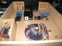
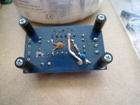
Now, the amazing thing is that even though the cables are a complete mess, I didn't have any hum or noises of any kind. I introduced hum last night when I added the two pieces of aluminum foil to the gaps between the heatsinks and the sheet holding the switch and volume pot.
All this issues will be addressed when I put this thing in a enclosure, but I need you guys help in the meanwhile. Can you please tell me where the ground loops are?. Can you please tell me if soldering ground cables to the heatsinks will get rid of the hum I have now that I didn't have before?.
Thank you, Lanchile.
Remove the aluminum foil and see if you still have the noise! Please post pictures to see it better how you have it now. I would not use aluminum foil inside amp, because it can get loose and fall on boards and make some trouble with all those live voltages.
My amplifier
Hi Aguilabrava ,
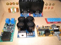
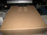
This is how I planned to build my amp. All parts are finished except for the amplifier boards. I need to add some parts of the Thiele network and also a 220 nf capacitor. It is fully remote controlled, but can also be manually controlled. There are going to be 4 inputs. It has a speaker protection against DC current. This protection board also has a switch-on delay to prevent pops and clicks when powering up the system. In the back (left side) you can see the inductors I made myself, just like peranders advised me (post #177). I'm not able to measure the inductance because I have no equipment for this, but I think they will do just fine.
Hi Aguilabrava ,
This is how I planned to build my amp. All parts are finished except for the amplifier boards. I need to add some parts of the Thiele network and also a 220 nf capacitor. It is fully remote controlled, but can also be manually controlled. There are going to be 4 inputs. It has a speaker protection against DC current. This protection board also has a switch-on delay to prevent pops and clicks when powering up the system. In the back (left side) you can see the inductors I made myself, just like peranders advised me (post #177). I'm not able to measure the inductance because I have no equipment for this, but I think they will do just fine.
Attachments
Speaker connections
As I mentioned in my last post I'm going to use a speaker protection kit. According to the manual of this kit the speakers should be wired as in the image. Should I place the second part of the thiele Network (the parallel RL circuit). In front of the speaker protection board or after it?
As I mentioned in my last post I'm going to use a speaker protection kit. According to the manual of this kit the speakers should be wired as in the image. Should I place the second part of the thiele Network (the parallel RL circuit). In front of the speaker protection board or after it?
Attachments
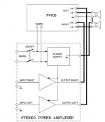
The R//L can go before the spkr prot, or after the spkr prot. Both work equally well.
The Zobel half if fitted before spkr prot must go as close to the output pins and chip decoupling as possible.
If you fit the Zobel after the R//L, then the Zobel is directly across the Amplifier's spkr output terminals.
The Zobel half if fitted before spkr prot must go as close to the output pins and chip decoupling as possible.
If you fit the Zobel after the R//L, then the Zobel is directly across the Amplifier's spkr output terminals.
It is preferable to place both circuits on the amp side of the relay. That way their protective function remains in place even if the relay cuts the signal to the speakers. Oscillation or RF interference may not bother you when the speaker is disconneceted, but that is no reason to subject the amp to either.
You also avoid discharging or recharging the snubber capacitor each time the relay changes state. Voltage and current involved are small, but so is the capacitor and there is no need to age it faster than necessary.
Normally at least the snubber will be on the amp board and the protection circuit will be on a different board, so that issue usually solves itself.
If you fit the snubber behind the R//L circuit, you go from a 1st order to a 2nd order low pass with a highish Q that may just lead to the oscillation the snubber is there to avoid among other things.
It is important to understand that the RC circuit is not a Zobel network, i.e. it is not an impedance correction. The capacitor value is far to small for that. It is an RF snubber. It should be close to the amp, not close to the speaker.
The Thiele Network is in two forms.
Form1:
R+C across the amplifier output and R//L on the route to the speaker terminals.
Form2:
R//L on the route to the speaker terminals and the R+C across the speaker terminals.
Both these versions work. That is the way Thiele designed it.
Cherry followed up with a short paper explaining that there are an infinite number of intermediate versions that span from the two limiting forms that Thiele proposed.
I have posted the spreadsheet to allow the two Thiele forms to be calculated and for all the intermediate Cherry versions to be calculated.
Yes, but with different values.Both these versions work.
Nice. Where?I have posted the spreadsheet
http://www.diyaudio.com/forums/solid-state/94029-when-output-inductor-needed.html#post1105724
Download the zip file. It is simply a compressed Excel XLS file.
Download the zip file. It is simply a compressed Excel XLS file.
Last edited:


Hi Guys:
I'm sorry I haven't been able to post lately, I've been very busy trying to keep my head out of the water...
Pemo, where did you find that board?. Where is it being sold?.
As you all know, I am far from being an expert in this matter, but when you mention a filter in the input, are you referring to the C7 of this new board?. If that is the case, our XY boards have that same capacitor called C5.
I think you are right about the RC network, R1 and C5 in this new board. I also see two additional capacitors, C3 and C4, obviously film type, located right next to C1 and C2, which are the same C1 and C2 caps in our XY boards but ours lack these two extra film caps. Their function is a question to AndrewT and Pacificblue. All I can say is that they look like those small film caps in front of the big electrolytics in the PSU.
I also see that the grounds seem to be properly separated, there is no need to "cut any trace bridges" on these, at least I think so, but the experts have the last word on this too.
Anyhow, it looks very interesting, the only thing I don't like is the location of the input filter cap, there is no room to place a large axial polypropylene capacitor in there, I guess it would have to be a Wima or something of that sort, other than that these looks like a much better board than the XY. Pemo, thank you for sharing. Could you please post the link to the seller of these boards?.
Corpius:
Your amp looks great, I like the way you implemented the RC network and the RF filter capacitor. Next time I build one, I will definitely use your method. I also like your idea of placing the R//L network on a PCB board. What I don't like is the components used, for the RF capacitor and RC network capacitor I have read that the ideal is to use a good quality film capacitor. Also, metal film resistors are said to be much better than carbon ones. But, other than that, it looks very nice.
Did you finish it?. If so, how does it sound?.
I am trying to upgrade mine, I want to get some Kendeil 15000uF capacitors to replace the Nover ones that came with my PSU. I am also still working on getting the enclosure, but before I do that I'm going to need help balancing the two 15V secondaries in my transformer so I can use my input selector board and the speaker protection board. I was able to resolve the "hum" issue I had lately, it was caused by one of the pieces of aluminum folder I placed between the heatsinks and the chassis, it was touching the side of the ON/OFF switch, I folded it a little bit so it wouldn't touch the switch and the hum was gone. My amplifier sounds great!
Please let me know if you are done with yours, and how it sounds. I wonder if Fabricated and the other guy, I forgot his nickname, have finished their amps...?
R1C5 is the output Zobel.
R5C7 is the input high pass filter.
R6 can be used for the input low pass filter, but you need a cap parallel to R5 to complete this.
C8 +ve Pin is probably connected to Power Ground on the underside.
C3 & C4 are the HF decoupling. C4 is too far away from the power pins.
R5C7 is the input high pass filter.
R6 can be used for the input low pass filter, but you need a cap parallel to R5 to complete this.
C8 +ve Pin is probably connected to Power Ground on the underside.
C3 & C4 are the HF decoupling. C4 is too far away from the power pins.
Last edited:
No, I'm not an artist at all. Have you taken a closer look at my soldering? There is still lots of resin on the board, but I just learned that this can easily be cleaned using 2-propanol. Good thing that I work i a laboratory where lots of this secondary alcohol is used.Corpius:
I forgot to mention that your inductors look great, you are an artist... I bought mine already made because I don't think I would've been able to do such a nice job...
")
I also used a lead free solder containing silver. This didn't flow nice into the pcb's holes so I had to heat things quite long to make a good soldering joint. It gave a lot of mess. Lots of resin on the boards and it didn't stick well to my soldering tip. Very quickly resulting in a dirty soldering tip. No I used 60/40 solder. With lead!! This resolved all problems I encountered during my soldering. I thought for a long time that soldering is very hard to learn because of my poor results, but when using some good solder it becomes a lot better.
The making of the inductor was quite easy. I followed the values (diameter and number of windings) perandersen posted i while ago. I found a marker that had the right diameter and bought some enameled copper wire. Actually quite a lot, because 500 grams was the smallest spool I could find. Now I have about 480 grams left over for future projects. After winding them around the marker my fingers were a bit sore. I suppose you easily make them like I did.
I have still not hooked everything up, because my mind was on other things lately. Hospital visits and a Twisted Pear Audio - Buffalo DAC. This amp was just a side project to become more skillful and learn some more about electronics. nevertheless I will start finish it and still hope it is good. this afternoon I'm going to do some testing with the input selection and volume boards. I'll keep you posted when making progress.
Last edited:
Just a promised a update on my progress. Just testes the remote volume control and input selection. It all works great. Not that this is really needed., but now I just need to build a debouncing circuit for in rotary encoder.
I uploaded a video to Youtube.
Remote volume control and input selection - YouTube
I uploaded a video to Youtube.
Remote volume control and input selection - YouTube
what makes the difference to 60/40 tin/lead?Buy and use 63/37 tin/lead solder.
60/40 is not electronic component solder.
It is a pasty solder, i.e. it does not have a melting point.
60/40 has a melting range and while the solder is in that temperature range it becomes pasty. If disturbed during this pasty phase, the joint does not "make" properly. It will lack electrical bonding and it will lack strength.
63/37 is the eutectic solder used for electronic components.
Eutectics and there are many of them do have a melting point. They do not have a pasty phase.
Last edited:
Corpius:
AndrewT, one more time is absolutely right regarding the solder you are using. If you do a little research you will find tons of documents telling you about all disadvantages of the 60/40 solder and why it shouldn't be used.
I went through the same issues you did, I had never soldered anything before these XY boards, I practiced with old video cards and motherboards before soldering the XY LM3886 boards. I thought soldering was hard, but as you, I discovered I was using the wrong soldering iron and the wrong solder. Once I changed those two, things became a lot easier and better. I used an adjustable soldering station I bought online, very good quality, and for the solder I used Cardas Quad Eutectic, very good solder, it melts very nice, very clean, it is composed of tin, copper, silver and lead, that's why it's called Quad Eutectic. I highly recommended it. I also used 91% alcohol to clean the resin flux left on the boards, but it wasn't too hard because the Cardas solder is very clean.
- Home
- Amplifiers
- Chip Amps
- Bought a XY LM3886 Kit.