Where did the 3886 come from?
Was it China or similar disreputable country?
China indeed. The LM3875 kit came from the USA. This one is working flawlessly. Volume control and input selection via remote control is also working as supposed to be. Now all i have to do is finish the chassis and rewire it all in a neatly way.
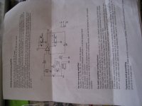
This kit also came with a manual. The China kit did not
Attachments
You interrupted signal ground and power ground on the PCB by scratching away the thermals. Now the signal ground is floating. That is the reason why the output swings to one rail.
You need a connection from signal ground to the power ground. For a test take a wire from the IN GND terminal to the OUT GND terminal and check, if that solves the issue.
You need a connection from signal ground to the power ground. For a test take a wire from the IN GND terminal to the OUT GND terminal and check, if that solves the issue.
That sounds plausible. I thought I did it just like Aguilabrava did. I guess I did it wrong. I will try it later this week. Thanks for your reply!You interrupted signal ground and power ground on the PCB by scratching away the thermals. Now the signal ground is floating. That is the reason why the output swings to one rail.
You need a connection from signal ground to the power ground. For a test take a wire from the IN GND terminal to the OUT GND terminal and check, if that solves the issue.
I do not get it. Are you trying to tell me that the input ground needs to connect to the power ground? Why where the bridges cut then?Corpius, by looking at your pictures you did cut the ground bridges the right way, I think what Pacificblue is telling you is that ALL grounds need to be connected so the input GND isn't floating. Just connect the GND's and test again.
By the way, when I talk about the quality of the components of these XY LM3886 kits, I'm basically referring to the very cheap and low quality electrolytic capacitors included in the kit, and the resistors which are good quality metal film but way too small, I have read that the ideal wattage in the resistors for this type of amplifiers should be 1/2 watt.
Now, when I ordered the kit I kind of knew this, the two PCB's including the two LM3886TF and everything else sells for $17.99 with free shipping from China. Each LM3886TF here in USA sells for $8.50 plus shipping, so even if one has to discard those horrible capacitors and replace the resistors with bigger ones, it is still a bargain. I used the PCB's, the LM3886TF's and the connector blocks, everything else was upgraded and my amplifier sounds just great.
Now, when I ordered the kit I kind of knew this, the two PCB's including the two LM3886TF and everything else sells for $17.99 with free shipping from China. Each LM3886TF here in USA sells for $8.50 plus shipping, so even if one has to discard those horrible capacitors and replace the resistors with bigger ones, it is still a bargain. I used the PCB's, the LM3886TF's and the connector blocks, everything else was upgraded and my amplifier sounds just great.
An attempt to avoid possible ground loops.I do not get it. Are you trying to tell me that the input ground needs to connect to the power ground? Why where the bridges cut then?
I will give it a try later on this week. Thanks againAn attempt to avoid possible ground loops.
Fabricated:
No, I don't have any pictures of the amp and speakers but I will post some soon.
I am working right now on making some improvements, I bought 2 more XY Amp PCB's and 2 of the ones Pemo found and 1 Power Supply PCB, in the amp PCB's I am going to install better electrolytic capacitors, I bought some Nichicon Fine Gold, Elna Silmic II, Jantzen MKP Crosscap and Wima MKS. In the Power Supply PCB I'm going to install 4 Cornell Dubilier 18000uF 50V electrolytics, a 1000V 50A bridge rectifier with heatsink and all the high frequency filter capacitors Wima and Faratronics.
I'll be using a bigger inductor and resistor in the R//L network as suggested by AndrewT and Pacificblue. I also purchased a couple of aluminum heatsinks for the LM3886's, much bigger and robust than the ones I got for the original kits. This is just to experiment, I've been reading a lot about power supply designs and how all these components influence the quality of sound.
I want to try these options before I move on to the enclosure phase, I still have to resolve the power issue with the input selector and speaker protection boards. If these changes make this thing sound better it's going to be amazing because it really sounds great as it is right now. I will post pictures when I have all these assembled.
Fabricated:
If these changes make this thing sound better it's going to be amazing because it really sounds great as it is right now. I will post pictures when I have all these assembled.
I really think that if there's any sonic improvement, it won't be noticeable unless you have equipment to check it. On the other hand, longevity, this might be an amplifier that will last a long long time without problems.
RGDS
PEMO

Hi:
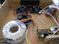
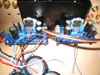
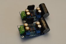
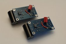
Here, the pictures of the new XY LM3886 amps I just put together yesterday.
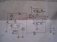
The C1, C2, C3 are now Nichicon Fine Gold 100uF 50V, C4 is Elna Silmic II 47uF 50V. Ri (Inverting input resistor) was originally a 1K Ohm metal film but in these new amps I used a high quality japanese 680 Ohm carbon composition resistor. C5 was also replaced by a Jantzen Audio Cross Cap 4.7uF 400V. The Zobel R+C is now a 10 Ohm metal film resistor with a Wima MKS-2 0.22uF 250V, and the RF input cap is now a Faratronics polyester film 1nF 100V.
***In the pictures, the Zobel R+C is wrong, I placed the capacitor first, then the resistor, but the mistake has been corrected.
I used the "Corpius Method" to do the modifications in these new boards.
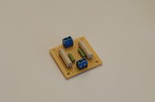
I also upgraded the R//L Thiele with bigger 1.5uH inductors and 2 high quality japanese carbon composite 10 Ohm 2W resistors, using the "Corpius Method" too, soldered on a PCB board I got at Radio Shack.
Here, the pictures of the new XY LM3886 amps I just put together yesterday.
The C1, C2, C3 are now Nichicon Fine Gold 100uF 50V, C4 is Elna Silmic II 47uF 50V. Ri (Inverting input resistor) was originally a 1K Ohm metal film but in these new amps I used a high quality japanese 680 Ohm carbon composition resistor. C5 was also replaced by a Jantzen Audio Cross Cap 4.7uF 400V. The Zobel R+C is now a 10 Ohm metal film resistor with a Wima MKS-2 0.22uF 250V, and the RF input cap is now a Faratronics polyester film 1nF 100V.
***In the pictures, the Zobel R+C is wrong, I placed the capacitor first, then the resistor, but the mistake has been corrected.
I used the "Corpius Method" to do the modifications in these new boards.
I also upgraded the R//L Thiele with bigger 1.5uH inductors and 2 high quality japanese carbon composite 10 Ohm 2W resistors, using the "Corpius Method" too, soldered on a PCB board I got at Radio Shack.
Attachments
Now, when I replaced the 2 old amps with these 2 new to test them, one of them didn't work, as soon as I turned the switch ON I heard a loud thump in one speaker, then no sound at all. Even though there was no sound coming out of the amp, it got super hot in a matter of seconds, while the other one worked fine and didn't get hot at all because the volume was low. I removed the bad one and replace one of the old ones to test, I can't really find any sonic difference, the only one is at very low volume level, the new amp seems to reproduce high frequency much cleaner, but at medium and high volume, I can't tell the difference.
There is another issue, the new amp has hum, very mild, but if I get my ear close to the speaker, I can hear it, the old amp has no hum at all, I wonder if this has anything to do with the way the mods were done this time... Anyhow, I have to fix the wire mess I have in the temporary chassis I am using, it might be that.
I checked all component values on the new amp that didn't work, also continuity, I can't find what's wrong with it. I'm going to try to desolder it using something called Chip Quick, I tried this before with one of the old ones using a vacuum pump and the soldering iron and it was impossible, hopefully I'll be able to do it with this Quick Chip stuff.
And, NO, none of these components came from China except the PCB boards, some came directly from Japan, others from a couple of the big electronic component supplier here in US.
Is there any way to test the LM3886 chip before soldering it to a PCB?.
In a series connection it does not matter which one comes first. It works either way.***In the pictures, the Zobel R+C is wrong, I placed the capacitor first, then the resistor, but the mistake has been corrected.
Could the components you soldered to the bottom with the unisolated leads be creating a short somewhere?it got super hot in a matter of seconds,
You coupled a speaker before you proved the amp was working properly !!!!!
You powered up a mains powered project without using the bulb tester !!!!!
You deserve all you get.
Yes, Andrew, you are right, that was really stupid of me, luckily I didn't damage the speaker, the amp just made that loud thump sound and got super hot, while the other one played music normally and didn't get hot at all. I am a very impatient person, as soon as I finished soldering the components I was dying to hear the sound, because of being impatient is why I soldered the R+C network the wrong way the first time, then it took me extra time to desolder it and correct it.
What do you think it's wrong?. Is there any chance that the LM3886 could be defective?. All the components are from reputable suppliers, the electrolytics are fresh, I have checked every solder joint, every value, continuity, everything seems to be fine.
I asked if there was a way to test the LM3886 for functionality before soldering it to a PCB, nobody has answered, but I found these two quotes below from Pacificblue in another thread in this site:
"Desolder the IC and measure continuity between the output and the supply pins. If you have continuity, replace the IC."
"In one direction, yes. You should get continuity, if the mulitmeter's com is connected to 3. With the com connected to either 1 or 5 there should be no continuity. "
I'm going to try that as soon as a desolder the LM3886, if I'm able to do it, I already tried once and it was impossible, let's see if that Chip Quik thing helps...
Any other suggestions?.
In a series connection it does not matter which one comes first. It works either way.
Hi Pacificblue:
Thank you, if I would've known... I hate everytime I have to desolder something because it is so much harder than soldering... But thanks, now I know for next time.
Could the components you soldered to the bottom with the unisolated leads be creating a short somewhere?
I thought about that, the wire that goes from pin #3 to + Output seats on top of R2 in the upper end, I checked continuity between them and there is none. I am trying to determine what is wrong, I got some of your posts at another thread where another user was having big DC offset values, you suggested what I posted above, and also that one or more capacitors could be defective. How do I determine that?. Every solder joint looks OK, I can't find nothing wrong.... It is a shame because all these components I bought now are more expensive than the ones I used the first time, supposed to be much better quality, and all from reputable sources... I'm a little disappointed, I know something is causing this issue, I'm having a problem finding out what it is...
Aguilabrava - When testing a new build next time, be sure and check your AC and DC voltages as you go along. In other words, don't apply power to the amp modules until you're sure the tranny is putting out the correct AC voltages and the PSU is putting out the DC voltages you are expecting (no load). They will likely be a little lower under load. This way you will avoid any surprises and possibly avoid a couple of blown amps, or worse yet damaged speakers.
Note: If you have a well-regulated bench power supply that outputs say, +-24VDC, you can use it to 'pre-test' the amp modules. Even if the output voltages are lower than what you will normally be operating it with, it will work good enough to test your amp. I know they can be expensive so not everyone has one handy.
If everything reads as expected, next connect the amp modules to the PSU - ONE channel at a time with no speaker connected. Using your VOM, or DMM set it to read DC voltage around 200mV or close to that range as possible. You will be testing the amount of DC-Offset the amp has. Clip the test leads to the speaker terminals of the amp module. Power up the bench supply, or amp PSU. Let the amp settle in for a few minutes. The readings will fluctuate a little, but will generally settle down to a very low reading of say < 10mv. That's good. You may also even get a negative (-) reading. That's ok too. If you get a very high voltage reading >100mv or worse, something is clearly wrong. Repeat the same for the other channel.
Hope this helps you and others before connecting everything up in our excitement to hear what our new amp sounds like. Plus it's just good practice before possibly destroying a lot of work, and possible frying a couple of speakers.
I'm posting a portion of a DC-Offset thread from over at Audiokarma. Credit for this goes to Echowars as he continues to educate us all on the benefits of low DC-Offset. His full post can be found here. It's worth reading. Safe building everyone.
"1. Speakers disconnected (or connect the meter to the 'B' speakers and set the front panel speaker control accordingly)
2. Input set to an unusued position (not Phono)
3. Volume control at minimum.
4. Balance in center
5. Tone controls either defeated or set to mid position
6. Set your meter to read DC, and set to a low scale (300mV scale is common) Connect directly to the Pos and Neg of the speaker terminals
7. Give the amp 10 minutes to settle.
If you read:
0 - 15mV: Damn good!! If you read '0V', you may have a capacitor output, or your meter is set wrong
16mV - 50mV: An acceptable value, especially at the lower end of this range. 2nd harmonic distortion is probably twice to four times what manufacturer's spec calls for at higher frequencies. Probably not audible, as the distortion is mostly in the upper octaves. At the upper end of this range I begin to raise an eyebrow.
50 - 85mV: Something is certainly amiss, and while this is not enough to put your speakers or equipment in jeopardy, the amp is running nowhere near where it should. I'd venture to guess that most of the DC-coupled amps that are in use by forum members here fall into this range.
100mV to ?: A high enough voltage will cause the DC protection to kick in. This happens at a level determined by the designer, but is usually equivalent to about a diode drop (600mV)or so. Needless to say, if you are listening to an amp with 100mV or more of DC offset, you have no idea what the amp really is supposed to sound like. Indeed, some amps without a differential input are actually designed to have a bit of DC at the outputs, but this is triple-rare, and I don't think anyone here owns one. (in my book it's ****-poor design, but if you can sell it WTH..) "....
Edit... Aguilabrava, I know this may not help your current issue, or resolving it, but I thought it was worth noting for everyone here when it comes to observing best practice.
Last edited:
- Home
- Amplifiers
- Chip Amps
- Bought a XY LM3886 Kit.