The truth is, it's not my model. Thanks for them Bob and other people.
DropMeFiles ? free one-click file sharing service
Tell me, is the right model, I could be wrong.
It was mentioned before, when you say 'model' you should say 'schematic'. A model is a description of a device (transistor, diode, resistor) in mathematical terms for the simulator.
Models are never exact and therefor sim results can be very much different then real circuit.
It would help communication if you would follow this use of terms.
Jan
Hi guys,
Happy new year to start
Can someone help me out with the 2sk134 and 2sj49 mosfet models, so I can complete Bob's DH220C modification.
I post the .asc file here, using a bjt ops, if you are interested.
http://www.diyaudio.com/forums/solid-state/31131-hafler-dh-200-220-mods-134.html#post4932974
I have since added the DC servo and the CFP Vbe multiplier, see attched
Thanks
Rick
Hi Rick,
Here are the LSK489 and LSJ689 JFET models I used in the input stage.
Cheers.
Bob
Attachments
Here are the LSK489 and LSJ689 JFET models...
XTI=0 seems a bit odd, no temperature dependence for (gate) saturation current?
Also the two LSK489 models have different IDSS in the comments but have identical DC parameters?
Best wishes
David
Last edited:
Hi, Bob.Hi T117,
Nearly everyone here knows that I am a strong advocate of using SPICE simulation, especially with LTspice. Most of the time, LTspice gives you a very accurate result for the models and circuits that you give it. However, models are a constant shortcoming, even when they are created carefully. I have suffered at the hand of bad manufacturer's models and that is why I put a great deal of effort into creating my own. This does not mean that my models are the world's best. I just believe that they are just less inaccurate than the manufacturers' models for the parts I modeled.
SPICE results are inherently limited by the accuracy of the models and by the absence of most real-world parasitics in the schematic.
The greatest value in SPICE simulation is the insight that it gives and the ability to see cause and effect, and to avoid errors, and to enable evaluation of different circuit topologies.
One of the weaker aspects of using SPICE is to evaluate distortion in an absolute sense. I have had SPICE simulations give both higher and lower distortion than the real-world circuit. As an example, when I design a MOSFET power amplifier without MOSFET models that model subthreshold conduction, the simulated distortion may actually be higher than in the real-world circuit. That having been said, it is still extremely valuable in evaluating circuit distortion and the changes in circuit distortion that will result if various circuit changes are made.
Cheers,
Bob
I don't agree. I disagree only in the sense that your model is still one of the best I've seen. Quite possibly, they are the best in the world. I can see it in the fact that their use in the model of the amplifier are greatly increased distortion, from 40 to 60 dB. Therefore, I always try to use your model. I see in your models your work.
The rest, I agree. The simulator gives the circuitry indicative rating "better or worse". I found a border of the veracity of his calculations. I think, that the distortion caused by changes of regimes (collector current and voltage collector-emitter) during the period of the signal. Simulator sees these changes very well. We should only reduce them - for this we need the knowledge in schematic.
What do you mean by the term quasi-saturation?Read it in notepad.
* _kq - My models which have quasi-saturation!
Thanks, your models are very realistic. The data of the distortion schematic (thank you, jan.didden20KHz
I used the model library attached. It is mostly hand-made models. Read it in notepad.
") ) are in good agreement with the data of the sound card.
) are in good agreement with the data of the sound card.An externally hosted image should be here but it was not working when we last tested it.
TotaI Harmonic Distortion: 0.000014 %(0.000000%)
You need to check the currents of idle 100 mA from each of the output transistors.
Attachments
Last edited:
Output gate stoppers omitted. Output Zobel and the Pi filter omitted. Cross coupled gate protection omitted.Hi guys,
Happy new year to start
Can someone help me out with the 2sk134 and 2sj49 mosfet models, so I can complete Bob's DH220C modification.
I post the .asc file here, using a bjt ops, if you are interested.
http://www.diyaudio.com/forums/solid-state/31131-hafler-dh-200-220-mods-134.html#post4932974
I have since added the DC servo and the CFP Vbe multiplier, see attched
Thanks
Rick
Output source resistors added. Various degeneration resistors added.
Are the diodes across the LTP in the correct position? Or does the location above, or below, the cascode not matter?
Last edited:
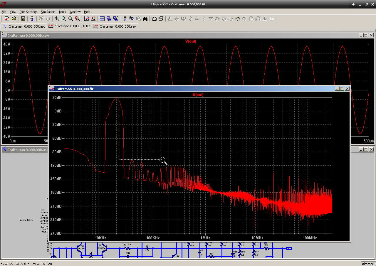
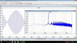
the plot is showing signal @ ~+30dB.Thanks, your models are very realistic. The data of the distortion schematic (thank you, jan.didden
An externally hosted image should be here but it was not working when we last tested it.
TotaI Harmonic Distortion: 0.000014 %(0.000000%)
You need to check the currents of idle 100 mA from each of the output transistors.
The 2nd and 3rd are at ~ -110dB.
These two distortions are ~ -140dB ref signal.
add them together and you get ~-134dB, then add on all the other distortions. what do we get -133db or -132dB or -130dB?
But convert 0.000014% to dB and I get -137dB
That indicates an error of at least 5dB.
What does not add up?
Last edited:
Happy New Year to everyone!
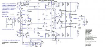
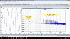
Attached 100W CFA. Simulated THD is below 1 ppm at all frequencies and and all output power (before clipping). At 1 kHz is below zero, or below LTspice simulation capabilities.
The Loop Gain looks as VFA one but it's pure CFA, pay attention how the compensation made, I called it Output Inclusive Two Pole Compensation (I've never seen it used in in any other amplifier). With this kind I am getting best result with distortion and stability.
In my opinion it's not possible to make it simpler with close ti its data.
Best wishes
Damir
Attachments
Two things don't add up. The simulator takes into account 20 harmonics of the signal 20K and gives the result in numbers. I think the computer knows how to count. Secondly, we don't hear harmonics above 20K. While the open loop gain increases and becomes approximately 120 dB down from 20K. All the distortion products, which fall into the audible range are suppressed much more than the harmonics 20K.That indicates an error of at least 5dB.
What does not add up?
These two distortions are ~ -140dB ref signal.
add them together and you get ~-134dB, then add on all the other distortions. what do we get -133db or -132dB or -130dB?
Andrew I think the convention is rss addition which would be -137dB (we are still in dbV here).
Happy New Year to everyone!
Attached 100W CFA. Simulated THD is below 1 ppm at all frequencies and and all output power (before clipping). At 1 kHz is below zero, or below LTspice simulation capabilities.
The Loop Gain looks as VFA one but it's pure CFA, pay attention how the compensation made, I called it Output Inclusive Two Pole Compensation (I've never seen it used in in any other amplifier). With this kind I am getting best result with distortion and stability.
In my opinion it's not possible to make it simpler with close ti its data.
Best wishes
Damir
Some additional FFT plots.
Attachments
DH-220c modification, ltspice sim
I have updated the design, using the feedback and models provided.
Set the ops bias I at 140mA per device.
Add the source R's in the ops, just so it is easy to see the idle I.
N-Period=1
Fourier components of V(vout)
DC component:-0.000159784
Harmonic Frequency Fourier Normalized Phase Normalized
Number [Hz] Component Component [degree] Phase [deg]
1 2.000e+04 2.105e+01 1.000e+00 -2.96° 0.00°
2 4.000e+04 2.820e-03 1.340e-04 176.71° 179.67°
3 6.000e+04 7.558e-04 3.591e-05 -84.09° -81.13°
4 8.000e+04 1.832e-03 8.702e-05 175.43° 178.40°
5 1.000e+05 2.747e-04 1.305e-05 22.07° 25.04°
6 1.200e+05 1.297e-03 6.165e-05 173.35° 176.31°
7 1.400e+05 8.281e-04 3.935e-05 59.48° 62.44°
8 1.600e+05 1.008e-03 4.791e-05 170.61° 173.57°
9 1.800e+05 1.066e-03 5.064e-05 61.41° 64.37°
Total Harmonic Distortion: 0.019286%(0.022617%)
Attachments
I have updated the design, using the feedback and models provided.
Set the ops bias I at 140mA per device.
Add the source R's in the ops, just so it is easy to see the idle I.
Thanks this is a great project to set up LTSPICE on my new computer, where are the models on Bob's site?
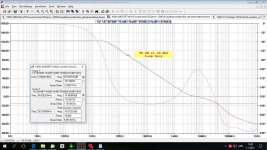
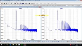
I want to say on the need to harmonize the output and input impedances of cascades. Schematic was posted earlier. Here's a graphic of loop gain of the amplifier in which the high output impedance of the first LTP, and high input impedance of the second LTP:
This amplifier has a second cascade (LTP) with low input impedance:
We can see the loss of 43 dB in the audio band and 33 dB at the frequency 20K. Obviously, this amp has more distortion than the first.
To achieve high loop gain is very difficult, but you can lose it very easily.
An externally hosted image should be here but it was not working when we last tested it.
This amplifier has a second cascade (LTP) with low input impedance:
An externally hosted image should be here but it was not working when we last tested it.
We can see the loss of 43 dB in the audio band and 33 dB at the frequency 20K. Obviously, this amp has more distortion than the first.
To achieve high loop gain is very difficult, but you can lose it very easily.
Last edited:
I want to say on the need to harmonize the output and input impedances of cascades. Schematic was posted earlier.
As before I'm sure this is YOUR amplifier there is no evidence that you have bothered to go through the effort to enter and analyze any alternative solution presented by others. In the spirit of teaching others what can be done I have decided to do it for you.
Last edited:
ltspice models
Yes, Bob's models are on his web site. I doubt that he has updated his web site with the new ones posted here as of late.
To make it easier for you and everyone, just unzip the attached and install in the ltspice default path.
C:\Program Files\LTC\LTspiceIV\lib\cmp
Yes, Bob's models are on his web site. I doubt that he has updated his web site with the new ones posted here as of late.
To make it easier for you and everyone, just unzip the attached and install in the ltspice default path.
C:\Program Files\LTC\LTspiceIV\lib\cmp
Attachments
As before I'm sure this is YOUR amplifier there is no evidence that you have bothered to go through the effort to enter and analyze any alternative solution presented by others. In the spirit of teaching others what can be done I have decided to do it for you.
Thank you Scott.
actually keeping a separate directory for 3rd party models is "cleaner", "easier for you and everyone" to keep clear what is being used and how to keep in sync
seeing .inc Cordell_Models.txt is a big clue
for few enough, short models just put them on the .asc - no chance of mistaken idendity or version then
seeing .inc Cordell_Models.txt is a big clue
for few enough, short models just put them on the .asc - no chance of mistaken idendity or version then
- Home
- Amplifiers
- Solid State
- Bob Cordell's Power amplifier book