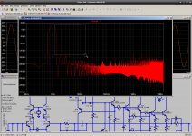
I know that. I have posted a spectrogram. According to my information, the simulator calculates the distortion accurately, since the level of 0.000,1% or more. You have achieved much more distortion, and the simulator is never wrong for levels of distortion at 0.002%. This is a very good simulator, but you can check out your advice to other simulator. It will show the same.Sorry to inform you simulators lie.
Last edited:
Hi Scott,
Yes. That's why the diamond buffer was in my mind to begin with. There's all kinds of stuff going on in that one.
Shouldn't the gates for J29 and 30 be tied to common?
-Chris
They are the stupid graphic fell between pixels, it's the minus input. This is kind of frustrating for me, years ago I spent hours of my own time trying to show how some simple circuits could get dramatic results and I went to the length of actually building them and publishing the results (always placing everything in the public domain).
You have achieved much more distortion, and the simulator is never wrong for levels of distortion at 0.002%.
I don't know what you are talking about, let's just stop.
The truth is, it's not my model. Thanks for them Bob and other people.you need to provide your models if you expect anyone to run that.
DropMeFiles ? free one-click file sharing service
Tell me, is the right model, I could be wrong.
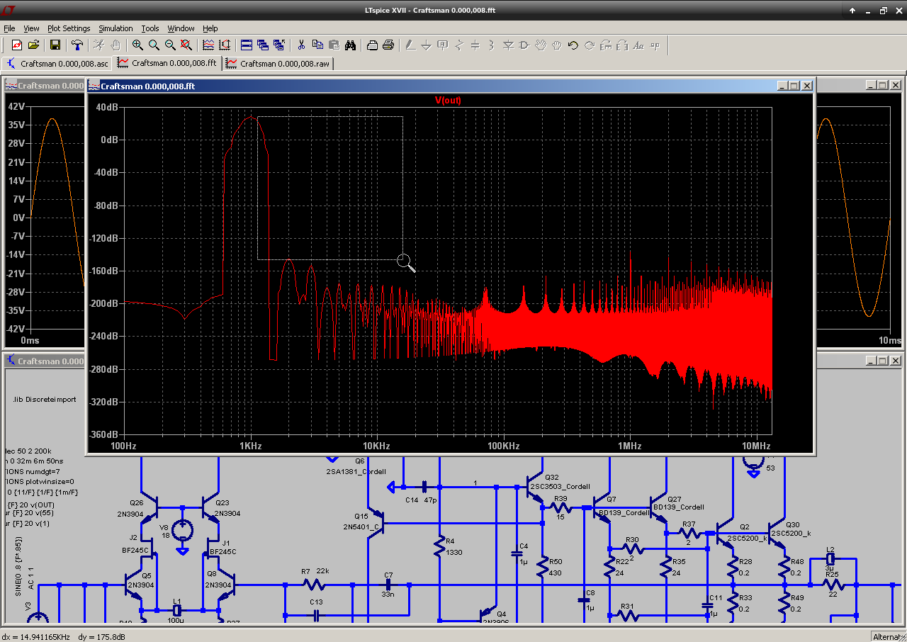
I take the model c THD = 0.000,008%
Maybe you meant 0.000008 without the %. I get this at 20KHz:
N-Period=1
Fourier components of V(out)
DC component:0.147388
Harmonic Frequency Fourier Normalized Phase Normalized
Number [Hz] Component Component [degree] Phase [deg]
1 2.000e+04 3.789e+01 1.000e+00 -3.81° 0.00°
2 4.000e+04 6.740e-06 1.779e-07 -167.26° -163.45°
3 6.000e+04 3.444e-06 9.090e-08 162.29° 166.10°
4 8.000e+04 5.395e-07 1.424e-08 2.47° 6.29°
5 1.000e+05 4.750e-07 1.254e-08 -22.93° -19.12°
6 1.200e+05 3.450e-07 9.106e-09 -63.73° -59.91°
7 1.400e+05 5.363e-07 1.415e-08 -150.73° -146.92°
8 1.600e+05 3.569e-07 9.420e-09 -40.65° -36.84°
9 1.800e+05 6.581e-07 1.737e-08 -149.39° -145.57°
10 2.000e+05 4.047e-07 1.068e-08 -32.10° -28.29°
11 2.200e+05 7.627e-07 2.013e-08 -151.94° -148.13°
12 2.400e+05 4.635e-07 1.223e-08 -22.16° -18.35°
13 2.600e+05 7.108e-07 1.876e-08 -150.71° -146.89°
14 2.800e+05 5.321e-07 1.404e-08 -13.23° -9.42°
15 3.000e+05 5.493e-07 1.450e-08 -146.24° -142.43°
16 3.200e+05 6.091e-07 1.608e-08 -4.96° -1.15°
17 3.400e+05 3.190e-07 8.420e-09 -133.08° -129.26°
18 3.600e+05 6.936e-07 1.831e-08 2.64° 6.45°
19 3.800e+05 1.433e-07 3.781e-09 -67.07° -63.25°
20 4.000e+05 7.854e-07 2.073e-08 9.61° 13.42°
Total Harmonic Distortion: 0.000021%(0.000000%)
1KHz:
N-Period=1
Fourier components of V(out)
DC component:0.147388
Harmonic Frequency Fourier Normalized Phase Normalized
Number [Hz] Component Component [degree] Phase [deg]
1 1.000e+03 3.738e+01 1.000e+00 -0.14° 0.00°
2 2.000e+03 9.830e-07 2.630e-08 107.40° 107.55°
3 3.000e+03 1.177e-07 3.150e-09 47.42° 47.57°
4 4.000e+03 4.663e-08 1.247e-09 -4.15° -4.01°
5 5.000e+03 3.974e-08 1.063e-09 -2.82° -2.68°
6 6.000e+03 4.338e-08 1.161e-09 -1.79° -1.65°
7 7.000e+03 5.222e-08 1.397e-09 3.71° 3.85°
8 8.000e+03 5.953e-08 1.593e-09 -1.05° -0.90°
9 9.000e+03 6.609e-08 1.768e-09 2.13° 2.28°
10 1.000e+04 7.392e-08 1.978e-09 -0.65° -0.50°
11 1.100e+04 8.026e-08 2.147e-09 1.55° 1.69°
12 1.200e+04 8.856e-08 2.369e-09 -0.30° -0.15°
13 1.300e+04 9.481e-08 2.536e-09 1.12° 1.27°
14 1.400e+04 1.032e-07 2.762e-09 0.01° 0.15°
15 1.500e+04 1.096e-07 2.932e-09 0.88° 1.03°
16 1.600e+04 1.179e-07 3.155e-09 0.28° 0.42°
17 1.700e+04 1.246e-07 3.333e-09 0.79° 0.94°
18 1.800e+04 1.327e-07 3.549e-09 0.52° 0.67°
19 1.900e+04 1.396e-07 3.735e-09 0.81° 0.95°
20 2.000e+04 1.474e-07 3.944e-09 0.75° 0.89°
Total Harmonic Distortion: 0.000003%(0.000000%)
Last edited:
Post #7932, The Vas this way cancels Cob errors by similarity making them common mode and not differential (in the signal path) doesn't anyone get it?
I think it's great, something similar could be done on amps with the LTP+CM type VAS such as the Goldmund (which is the only one I can name).
It is beyond me why someone would continue to argue with two or more master electrical engineers who have some 40 years of experience behind them.
But it does seem that someone shows up ever few month to do so.
You do not reach a high level of understanding without disagreeing with the highest authorities at least long enough to see your mistake. Granted, this doesn't have to be a stressful process.
I was still looking at the input mirror biasing
hadn't appreciated the diff pair VAS - I do see the cancellation now that it has been pointed out
I must confess to a bias against dual complementary stages in general given the hype about the symmetry
but in this case it is like devices that you are expecting the cancelling from rather than the N vs P halves
You do not reach a high level of understanding without disagreeing with the highest authorities at least long enough to see your mistake. Granted, this doesn't have to be a stressful process.
Yes but there is a difference between arguing to gain an understanding and arguing just to be right.
Or simply just arguing to make someone else wrong.
I have no reason to mystify someone and spread the model.Maybe you meant 0.000008 without the %. I get this at 20KHz: Total Harmonic Distortion: 0.000021%(0.000000%)
")
Maybe we use different models of transistors. Maybe too big the DC component of the output.Fourier components of V(out)
DC component:0.07435
Number [Hz] Component Component [degree] Phase [deg]
1 2.000e+04 3.789e+01 1.000e+00 -3.81° 0.00°
2 4.000e+04 1.540e-06 4.066e-08 -131.67° -127.85°
3 6.000e+04 2.187e-06 5.772e-08 173.10° 176.91°
4 8.000e+04 3.772e-07 9.956e-09 -31.02° -27.21°
5 1.000e+05 8.119e-07 2.143e-08 4.90° 8.71°
6 1.200e+05 3.054e-07 8.061e-09 -65.24° -61.42°
7 1.400e+05 2.917e-07 7.698e-09 6.16° 9.97°
8 1.600e+05 3.081e-07 8.131e-09 -49.65° -45.83°
9 1.800e+05 2.915e-07 7.695e-09 3.45° 7.26°
10 2.000e+05 3.234e-07 8.535e-09 -39.80° -35.99°
11 2.200e+05 1.710e-07 4.513e-09 -3.96° -0.15°
12 2.400e+05 3.501e-07 9.240e-09 -28.70° -24.89°
13 2.600e+05 9.213e-08 2.432e-09 -21.54° -17.73°
14 2.800e+05 3.892e-07 1.027e-08 -18.39° -14.58°
15 3.000e+05 5.489e-08 1.449e-09 -52.17° -48.36°
16 3.200e+05 4.403e-07 1.162e-08 -9.01° -5.20°
17 3.400e+05 4.588e-08 1.211e-09 -57.88° -54.07°
18 3.600e+05 5.023e-07 1.326e-08 -0.72° 3.09°
19 3.800e+05 5.759e-08 1.520e-09 -18.46° -14.64°
20 4.000e+05 5.737e-07 1.514e-08 6.54° 10.35°
Total Harmonic Distortion: 0.000008%(0.000000%)
DC component:0.147388
Sometimes this offset can also increase distortion.DC component:0.07435
Last edited:
It's not offset that causes false .four reports, it is drift. When the simulator solves the operating point correctly, there is no drift.
The .four command doesn't use a very powerful FFT window it seems, so it tends to be influenced more by drift than the FFT window when you use Hann, Blackman or Blackman-nuttal windows.
The .four command doesn't use a very powerful FFT window it seems, so it tends to be influenced more by drift than the FFT window when you use Hann, Blackman or Blackman-nuttal windows.
Hi guys,
Happy new year to start
Can someone help me out with the 2sk134 and 2sj49 mosfet models, so I can complete Bob's DH220C modification.
I post the .asc file here, using a bjt ops, if you are interested.
http://www.diyaudio.com/forums/solid-state/31131-hafler-dh-200-220-mods-134.html#post4932974
I have since added the DC servo and the CFP Vbe multiplier, see attched
Thanks
Rick
Attachments
Last edited:
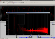
I know that. I have posted a spectrogram. According to my information, the simulator calculates the distortion accurately, since the level of 0.000,1% or more. You have achieved much more distortion, and the simulator is never wrong for levels of distortion at 0.002%. This is a very good simulator, but you can check out your advice to other simulator. It will show the same.
Hi T117,
Nearly everyone here knows that I am a strong advocate of using SPICE simulation, especially with LTspice. Most of the time, LTspice gives you a very accurate result for the models and circuits that you give it. However, models are a constant shortcoming, even when they are created carefully. I have suffered at the hand of bad manufacturer's models and that is why I put a great deal of effort into creating my own. This does not mean that my models are the world's best. I just believe that they are just less inaccurate than the manufacturers' models for the parts I modeled.
SPICE results are inherently limited by the accuracy of the models and by the absence of most real-world parasitics in the schematic.
The greatest value in SPICE simulation is the insight that it gives and the ability to see cause and effect, and to avoid errors, and to enable evaluation of different circuit topologies.
One of the weaker aspects of using SPICE is to evaluate distortion in an absolute sense. I have had SPICE simulations give both higher and lower distortion than the real-world circuit. As an example, when I design a MOSFET power amplifier without MOSFET models that model subthreshold conduction, the simulated distortion may actually be higher than in the real-world circuit. That having been said, it is still extremely valuable in evaluating circuit distortion and the changes in circuit distortion that will result if various circuit changes are made.
Cheers,
Bob
The greatest benefit from this occurs at 1KHz where the majority of distortion does in fact come from the Early effect on Q9. Of course by now all of this is buried in noise and the increasingly impossible job of the prototype designer is nowhere near finished.
-151.9db to -175.8db is a 24db (16x) improvement.
-151.9db to -175.8db is a 24db (16x) improvement.
Attachments
Last edited:
Hi guys,
Happy new year to start
Can someone help me out with the 2sk134 and 2sj49 mosfet models, so I can complete Bob's DH220C modification.
I post the .asc file here, using a bjt ops, if you are interested.
http://www.diyaudio.com/forums/solid-state/31131-hafler-dh-200-220-mods-134.html#post4932974
I have since added the DC servo and the CFP Vbe multiplier, see attched
Thanks
Rick
Hi Rick,
Here are the models that I recommend using. These VDMOS models use the LTspice parameter ksubthres to model sub-threshold conduction. I did the original simulations with ordinary VDMOS models and got sim results worse than my measured real-world results. I was actually in the process of creating these models today so that when I (finally) post the .asc it will simulate with these improved models.
Cheers,
Bob
Attachments
Hi Scott,
Between app notes and your own work, no one can doubt how hard you work to teach. I get it, and I'm sure many others do too. One good thing about an application note. You only have to argue with your peers. Now with simulators, everyone is an expert.
Thanks from the silent majority who understands at least some of it.
-Chris
That makes a whole lot more sense, thank you. I may not get the entire circuit, but I'm working on understanding it.They are the stupid graphic fell between pixels, it's the minus input. This is kind of frustrating for me, years ago I spent hours of my own time trying to show how some simple circuits could get dramatic results and I went to the length of actually building them and publishing the results (always placing everything in the public domain).
Between app notes and your own work, no one can doubt how hard you work to teach. I get it, and I'm sure many others do too. One good thing about an application note. You only have to argue with your peers. Now with simulators, everyone is an expert.
Thanks from the silent majority who understands at least some of it.
-Chris
- Home
- Amplifiers
- Solid State
- Bob Cordell's Power amplifier book