I'll be glad if it helps you.
 I'll leave off here. You clearly are not able to understand and I'm not going to dig out the measured performance and pictures again. You keep posting pictures of your own circuits clearly not interested in learning anything new. Several of your statements are simply wrong, and do I have to repeat the circuit as shown built with even 2N4401/4403 out of the bin works as stated. Bob's circuit works to0 he does not need your "help" either.
Last edited:
:lol: I'll leave off here. You clearly are not able to understand and I'm not going to dig out the measured performance and picture again. You keep posting pictures of your own circuit clearly not interested in anything new.
Language barrier?
Language barrier?
Thanks, somewhat maybe. I think more of doing things one way (which in my opinion leads to lots of added complexity) and not sitting down any weighing the tradeoffs of a different simpler approach to the same end. I'm a die hard Muntzer as Bob Pease put it.
BTW If I see it wrongly due to some misunderstanding I'm truly sorry. My take was that the comments suggested that the circuits posted don't work, this is just plain wrong. That could be a language barrier, for instance I took the phase comment as it's drawn wrong on the schematic.
PB2,
As I see in engineering often many just seem to lose sight of the end goals and end up over designing a product. I can see adding components if there is some real improvement or advantage but some just seem to be going for diminishing distortion numbers at any cost. If adding some components actually improves performance or perhaps makes for softer clipping or something that can be agreed upon is an improvement then go for it.
But as I said first many just seem to lose sight of what they are truly trying to do.
This is what I referred to as input-referred distortion analysis.
It is especially useful in assessing the distortion of the output stage, in-situ, with the feedback loop closed. If the closed-loop output distortion is very low compared to the distortion of the output stage (as a result of the global NFB), then the distortion seen at the input to the output stage is that pre-distortion required to make the output distortion nearly zero. The distortion waveform at this point is merely an inverted approximation to the distortion of the output stage.
Cheers,
Bob
Hi Bob, I notice that you don't use the term predistortion which is what a very old
timer professor used when I studied audio engineering. He pointed out that the distorted
waveform at the VAS output with the loop closed is the required distortion to cancel or
reduce the output stage distortion to that seen at the output. It is very counter intuitive
when looked at in the frequency domain since we add harmonics in order to have fewer
or reduced harmonics in the output. On the other hand, when looked at from the Vin/Vout
transfer function view it is obvious that a bend in the input to VAS section cancels a
bend in the output stage to make it more or nearly linear.
It is an interesting part of non-linear systems that I don't think is often understood.
There was an old AES article that provided the analysis and a circuit for predistorting a
signal for analog tape to correct for some of the tape distortion characteristics.
PB2,
As I see in engineering often many just seem to lose sight of the end goals and end up over designing a product. I can see adding components if there is some real improvement or advantage but some just seem to be going for diminishing distortion numbers at any cost. If adding some components actually improves performance or perhaps makes for softer clipping or something that can be agreed upon is an improvement then go for it.
But as I said first many just seem to lose sight of what they are truly trying to do.
I agree, and I have no problem with simulator experiments or even building complex
designs since it is a hobby and people have to get some enjoyment out of it. But that
does not seem to be what was going on in the previous posts.
It is also interesting to see what it takes to drive the distortion as close to zero as
possible but I never lose sight of how much distortion is actually audible.
Hi Bob, I notice that you don't use the term predistortion which is what a very old
timer professor used when I studied audio engineering. He pointed out that the distorted
waveform at the VAS output with the loop closed is the required distortion to cancel or
reduce the output stage distortion to that seen at the output. It is very counter intuitive
when looked at in the frequency domain since we add harmonics in order to have fewer
or reduced harmonics in the output. On the other hand, when looked at from the Vin/Vout
transfer function view it is obvious that a bend in the input to VAS section cancels a
bend in the output stage to make it more or nearly linear.
It is an interesting part of non-linear systems that I don't think is often understood.
There was an old AES article that provided the analysis and a circuit for predistorting a
signal for analog tape to correct for some of the tape distortion characteristics.
This is something that has been used in RF amplifiers where global FB can't be used, A very old technique. Does it make sense then to do this say before an output stage rather than relying on global FB to perform this function? And then why is it so important to linearize each stage if it's just going to bent out shape by the FB?
Predistortion is a very big thing with RF transmission these days with Quam256 and others. In fact, it is a topic that is being discussed in the RF community currently.
-Chris
RF can't be more off topic for this forum. So I'll just say this. The objectives for distortion reduction in RF are not the same as for the objectives for distortion reduction in audio.
A distorted RF carrier generates products which can interfere with adjacent channels.
As far as QAM is concerned noise is much greater problem. Same for all RF modulations.
Back to audio.
Hi Bob, I notice that you don't use the term predistortion which is what a very old
timer professor used when I studied audio engineering. He pointed out that the distorted
waveform at the VAS output with the loop closed is the required distortion to cancel or
reduce the output stage distortion to that seen at the output. It is very counter intuitive
when looked at in the frequency domain since we add harmonics in order to have fewer
or reduced harmonics in the output. On the other hand, when looked at from the Vin/Vout
transfer function view it is obvious that a bend in the input to VAS section cancels a
bend in the output stage to make it more or nearly linear.
It is an interesting part of non-linear systems that I don't think is often understood.
There was an old AES article that provided the analysis and a circuit for predistorting a
signal for analog tape to correct for some of the tape distortion characteristics.
I agree completely with you, and the term "predistortion" is exactly right. The only thing we have to keep in mind in the present case is that the predistortion is not created by a system block in a non-closed-loop way, but is rather "automagically" created by the NFB.
I also agree that it can be non-intuitive, but is certainly easier to understand in the time domain rather than the frequency domain.
It is also interesting to look at the predistortion at the input to the output stage as the output stage bias current is changed, or even as the amplifier warms up. It is easier to look at this larger-amplitude distortion than the often very low level of distortion at the output of the amplifier. At 1kHz, this is a good way to look at the static crossover distortion of the output stage. Within the frequency range where the NFB is effective, the spectrum and waveshape of this predistortion is also not skewed by the 6dB/octave loop gain roll-off.
Cheers,
Bob
True.
For audio, a diamond buffer pre-distorts the signal and the outputs distort it again in a complementary way. That applies to audio.
Not quite. A diamond buffer driver operates in Class A, while the output stage operates in class AB, and its primary distortion contribution is crossover distortion, which is not present in the diamond buffer.
Cheers,
Bob
Hi Bob,
I'm a little confused by your statement above.
-Chris
I'm a little confused by your statement above.
But we are talking about a diamond buffer, nothing else. A diamond buffer is at it's best when both stages remain in class A.its primary distortion contribution is crossover distortion, which is not present in the diamond buffer.
-Chris
Hi Bob,
I'm a little confused by your statement above.
But we are talking about a diamond buffer, nothing else. A diamond buffer is at it's best when both stages remain in class A.
-Chris
Sorry. I misunderstood you. I thought you were talking about a diamond buffer driving a class AB output stage.
Cheers,
Bob
diff pair and complementary pairs (in Class A) are the most common "distortion cancellation" subcircuits we have - with their even harmonic cancellation
beyond that implementing predistortion to cancel another becomes problematic to find, match and maintain the cancellation over operating range and normal variation
negative feedback is really the tool that we can push farthest with
beyond that implementing predistortion to cancel another becomes problematic to find, match and maintain the cancellation over operating range and normal variation
negative feedback is really the tool that we can push farthest with
Last edited:
diff pair and complementary pairs (in Class A) are the most common "distortion cancellation" subcircuits we have - with their even harmonic cancellation
beyond that implementing predistortion to cancel another becomes problematic to find, match and maintain the cancellation over operating range and normal variation
negative feedback is really the tool that we can push farthest with
Post #7932, The Vas this way cancels Cob errors by similarity making them common mode and not differential (in the signal path) doesn't anyone get it?
You keep posting pictures of your own circuits clearly not interested in learning anything new. Several of your statements are simply wrong.
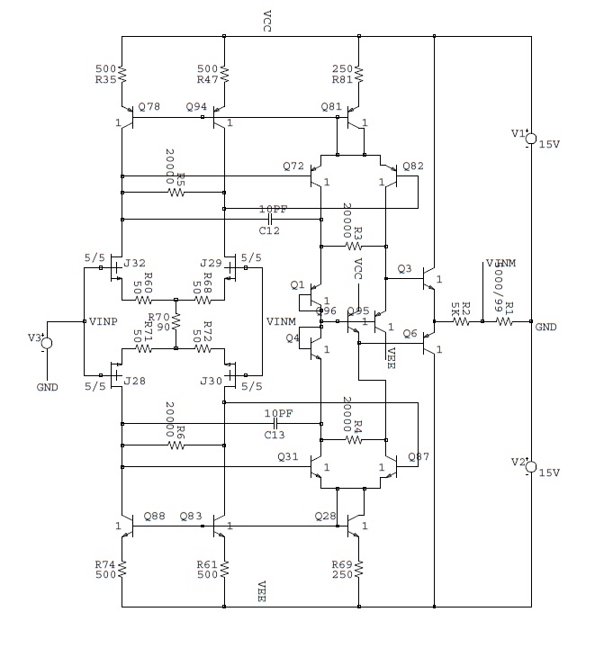
You suggested this circuitry.
An externally hosted image should be here but it was not working when we last tested it.
I explained, what I think and why.
I take the model c THD = 0.000,008%, and I removed followers VT16VT21, R28R34, area 4 (in the model - Q3Q10, R9R11). Oops! Distortion skyrocketed to 0.002%. The difference of 48 dB.
My boss will fire me for that! They shot me in the cellars of the KGB!
")
Then I add a 20K resistor, as your drawing R5 or R6. Distortion remains the same. This resistor is useless. It's just a waste.
I am attaching the model and see for yourself.
PS
Hill and Horowitz wrote in the book "Art of electronics": if an additional element improves the quality or parameter circuit, it should be set.
I'm doing that. I followed the advice of Hill and Horowitz.
Attachments
Last edited:
I take the model c THD = 0.000,008%
Sorry to inform you simulators lie. Again you fiddle with your circuit and report the results this does nothing for me you remove complexity from your circuit and it works less well that's your problem. Please don't appeal to authority I could care less whose advice you are following.
Last edited:
- Home
- Amplifiers
- Solid State
- Bob Cordell's Power amplifier book