Actual example
Hi all!
I have been following this thread with interest, because it came up just as I was designing the grounding for my new amp.")
To sum a few of the points up that I absorbed (I am sure I missed plenty of the details):
1. Check the current loops, and make sure they have clear paths (hence no diodes in the ground connection to the transformer)
2. Try to avoid multiple currents to one wire, because they will influence each-other.
3. (not really mentioned) try to make stars. Loops pick up radiation much easier.
4. When connecting to chassis earth, do this on a point where current total is zero.
5. The current coming through the diode bridge is high, with a pulsing character. (EMC!) Keep separate from all other signals.
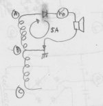
So, I am building an Aleph-X. This is a Class A amp, which makes things a lot easier, as current has a continious character. The design amplifies separate + and - signals to which the speaker is connected. So the speaker is not grounded, but is floating. (two resistors to earth keep it from floating too far from ground)
I made a schematic about the main currents. In the following post I will present my solution for the grounding paths.
Greetings, Harry
Hi all!
I have been following this thread with interest, because it came up just as I was designing the grounding for my new amp.
To sum a few of the points up that I absorbed (I am sure I missed plenty of the details):
1. Check the current loops, and make sure they have clear paths (hence no diodes in the ground connection to the transformer)
2. Try to avoid multiple currents to one wire, because they will influence each-other.
3. (not really mentioned) try to make stars. Loops pick up radiation much easier.
4. When connecting to chassis earth, do this on a point where current total is zero.
5. The current coming through the diode bridge is high, with a pulsing character. (EMC!) Keep separate from all other signals.
So, I am building an Aleph-X. This is a Class A amp, which makes things a lot easier, as current has a continious character. The design amplifies separate + and - signals to which the speaker is connected. So the speaker is not grounded, but is floating. (two resistors to earth keep it from floating too far from ground)
I made a schematic about the main currents. In the following post I will present my solution for the grounding paths.
Greetings, Harry
Attachments
Actual example
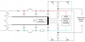
Part two: my solution.
The solution is why I want to have the opinion of this group, as it does not comply to most of the designs showed.
I do not presume to present the correct solution. But I would like to know is I made an error in my reasoning.
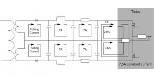
Most currents flow from the last positive capacitor to the last negative capacitor. Twice a 7A constant current that is biasing the mosfets. The PCB only takes 40 mA constant current, also between + and -.
The speaker is grounded with two resistors, these generate a maximum of 0,5A from + or - to ground.
The other currents are just feeding the last capacitors.
So, when I try to use the rules from the previous post, I end up not with a star point at the "center tap" of the transformer, but between the last two caps!
The other solution I could think of was running a lot of wires from each capacitor to the central tap, but still the two 7A currents that bias the mosfets have to go from ground capacitor- to ground capacitor +.
Did I make an error in my reasoning? Or is this a good design?
Greetings, Harry
Part two: my solution.
The solution is why I want to have the opinion of this group, as it does not comply to most of the designs showed.
I do not presume to present the correct solution. But I would like to know is I made an error in my reasoning.
Most currents flow from the last positive capacitor to the last negative capacitor. Twice a 7A constant current that is biasing the mosfets. The PCB only takes 40 mA constant current, also between + and -.
The speaker is grounded with two resistors, these generate a maximum of 0,5A from + or - to ground.
The other currents are just feeding the last capacitors.
So, when I try to use the rules from the previous post, I end up not with a star point at the "center tap" of the transformer, but between the last two caps!
The other solution I could think of was running a lot of wires from each capacitor to the central tap, but still the two 7A currents that bias the mosfets have to go from ground capacitor- to ground capacitor +.
Did I make an error in my reasoning? Or is this a good design?
Greetings, Harry
Attachments
MikeBettinger said:One other thought. Think of the supply as two +/- DC sources without charging currents, rectifiers or filter caps, only a +/- DC potential with a center tap. Where does the current flow?
Regards, Mike.
Hi Mike,
The way I think of it is that the large reservoir capacitors are the +/- DC sources, and that the amplifier currents flow to and from them and their common center node.
Bob
darkfenriz said:
EXACTLY !
I found transformer solution cheaper compared to electrolytic caps for doubling! These should be rather high value.
Adam
P.S.
A question:
Have anyone had any problems with double suplly rails at startup?
I assume small power regulated rails are charging slower at startup, so I've added some diodes so that early stages don't have lower voltage.
I am not sure if this is mandatory. Anyone?
Including diodes to make sure currents flow in the safe direction is a very good idea; 1N4004 diodes are cheap.
Also, make sure that currents flow in a safe and predictable direction when there is a fault, such as a blown fuse or shorted output transistors.
Also, if you play your cards right, you can use a Class-B transformer for the boosted supply and leave it on all the time, then use it's power as part of the soft-start circuit (or maybe even an auto-on circuit), as to operate a relay, if desired.
Bob
Christer said:Mike,
Let's just conclude that either we have some fundamental disagreement or, more probably, we misunderstand each other severely. So let's end the discussion here. It is not really important to me to sort this out and nobody else seems interested in the discussion either.
Agreed, Interesting response though. Having tried hard to make sure I understood what you were saying I have to assume that what I'm attempting to say in response doesn't fit your world view therefore it's not worth wasting any time on; especially if you can't convert me to your limited point of view.
I would have taken this more seriously if I thought for a minute that you had even tried to understand what I was relating.
To bad, I had an honest response to what was being discussed (again). What is supposed to happen (in my childish mind) is someone mutters bull, goes out and throws a current probe on the individual secondary connections to the centertap and either agrees or presents an intelligent response. What happened here was just a reiteration of basic powersupply theory from a textbook.
Just remember, it's not always you doing the judging in life.
I tried again, and thought my attempts to get it across clearly were getting better, but I'll go away now.
Regards, Mike.
Re: Actual example
Hi Harry,
Grounding is like religion, and five engineers will give you at least six different solutions. My view is this: Star grounding is good, but don't feel compelled to follow it religiously. When I think it is appropriate, I do star-on-star grounding, where a local star will close some current loops locally. Just remember to understand the nature of the current flowing in every wire, and what voltage drops it may be causing, and what those voltage drops may be doing to affected circuits.
Bob
harryeng said:Part two: my solution.
The solution is why I want to have the opinion of this group, as it does not comply to most of the designs showed.
I do not presume to present the correct solution. But I would like to know is I made an error in my reasoning.
Most currents flow from the last positive capacitor to the last negative capacitor. Twice a 7A constant current that is biasing the mosfets. The PCB only takes 40 mA constant current, also between + and -.
The speaker is grounded with two resistors, these generate a maximum of 0,5A from + or - to ground.
The other currents are just feeding the last capacitors.
So, when I try to use the rules from the previous post, I end up not with a star point at the "center tap" of the transformer, but between the last two caps!
The other solution I could think of was running a lot of wires from each capacitor to the central tap, but still the two 7A currents that bias the mosfets have to go from ground capacitor- to ground capacitor +.
Did I make an error in my reasoning? Or is this a good design?
Greetings, Harry
Hi Harry,
Grounding is like religion, and five engineers will give you at least six different solutions. My view is this: Star grounding is good, but don't feel compelled to follow it religiously. When I think it is appropriate, I do star-on-star grounding, where a local star will close some current loops locally. Just remember to understand the nature of the current flowing in every wire, and what voltage drops it may be causing, and what those voltage drops may be doing to affected circuits.
Bob
Re: Re: Actual example
The best reply I have ever heard. Thanks.
Bob Cordell said:Grounding is like religion, and five engineers will give you at least six different solutions . . . Just remember to understand the nature of the current flowing in every wire, and what voltage drops it may be causing, and what those voltage drops may be doing to affected circuits.
The best reply I have ever heard. Thanks.
Re: Re: Re: Actual example
Thanks, Babowana.
Here's my Question of the Day for you guys:
There are two popular ways of connecting the transformer-rectifier-reservoir capacitors to provide the pos and neg rails for a power amplifier. In the first, a center-tapped transformer has its center tap grounded, and its two arms go to the a.c. inputs of a single bridge rectifier, whose + and - outputs go to a pair of reservoir capacitors whose common node goes to ground. This is the most common and popular setup.
In the second, a transformer with two isolated secondaries is used (no center tap). Each secondary goes to a bridge rectifier. The pos and neg outputs of each bridge connect to a reservoir capacitor. The two reservoir capacitors then share a common node connected to ground.
Some claim that the second approach, which uses two bridge rectifiers, is superior. However, I have never seen a clear explanation of why it is superior. Indeed, the second arrangement appears to suffer an extra diode drop in the rectification process.
Is the second approach superior?
If so, why?
What are the tradeoffs?
Cheers,
Bob
Babowana said:
The best reply I have ever heard. Thanks.
Thanks, Babowana.
Here's my Question of the Day for you guys:
There are two popular ways of connecting the transformer-rectifier-reservoir capacitors to provide the pos and neg rails for a power amplifier. In the first, a center-tapped transformer has its center tap grounded, and its two arms go to the a.c. inputs of a single bridge rectifier, whose + and - outputs go to a pair of reservoir capacitors whose common node goes to ground. This is the most common and popular setup.
In the second, a transformer with two isolated secondaries is used (no center tap). Each secondary goes to a bridge rectifier. The pos and neg outputs of each bridge connect to a reservoir capacitor. The two reservoir capacitors then share a common node connected to ground.
Some claim that the second approach, which uses two bridge rectifiers, is superior. However, I have never seen a clear explanation of why it is superior. Indeed, the second arrangement appears to suffer an extra diode drop in the rectification process.
Is the second approach superior?
If so, why?
What are the tradeoffs?
Cheers,
Bob
Mike,
You seem to think that I was not serious and that I must be wrong and you right. That is a strange conclusion which I think shows even more that there is some serious misunderstanding even about what we are really discussing. I am not sure if there even is something to be right or wrong about, since I still don't really understand what you have been trying to say and you constantly ignore the question being repeated over and over again. Furthermore, I was never trying to convince anybody about anything, but just trying to understand you.
What happened from my point of view was that you made a claim about the center tap. Your argument for this claim was the problem, since it seemed to go against basic electricity theory. Several people
before me pointed this out and asked for a clarification of what you meant. However, you just reiterated things you had said before and seemed to either not understand the question or even avoiding it. Then I entered and made yet an attempt to ask for a clarfication, and once again you seemed to avoid or not understand the question. Since you do seem to understand EE well, your behvaiour puzzled me, since I would then presume that also you believe Kirchoffs laws hold for real circuits. However, it is obvious that there is a seious problem of understanding between you and some other people (including me). Something you said in one of you more recent posts gave me a feeling that you are using words and terminology in a way that seems very strange to me. Perhaps there are others who have understood what you mean.
However, it seems pointless to continue the discussion since there is obviously some fundamental misundestanding about what you have been saying and you do not seem to understand what it is that bother us others about your claims.
Hi, Bob,
I'm not EE, but I try to answer your "Question of The Day"
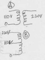
First, is it right that the first case is A and second case is B?
If it is right, then it makes sense if B is better (not perfect, but better than A).
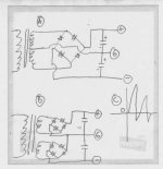
I've looked at osciloscope that music signal sometimes is like drawing C, where positive half and negative half are not the same magnitude. Let's consider an instance of the positive half.
In the case of positive half, the energy will flow from positive rail to the speaker to the ground. This will cause a "dip" in the positive rail.
In the case of A, if the positive dips, then the negative supply will also dip, because of the flux in the transformer will decrease wholy, making all +rail and -rail dips because of positive load to the speaker (then to the ground). This seems "not fair" for the negative rail, because the load is happening to the positive part (none is in the negative side), but making the negative rail dips.
This happens because the positive part-the ground-and the negative part is actually all 1 wire from top to bottom (like auto-transformer). If the "positive to ground" part is loaded, the "ground to negative" part will be disturbed much because of this "1 wire" system.
In the case of B, the negative dip (because of positive load) will be less, because it comes from fully different secondary winding. The effect is from less magnetic flux only, but none from "1 wire" system effect.
I said it is not perfect, because the better one is 1 transformer (+rectifier+cap bank) for positive rail and another transformer (+rectifier+cap bank) for negative rail. This way if positive load occurs, the negative side will not be affected (as long as the input electricity to the primary is not dropping voltage).
This also depends on the PSRR of the amp itself. The better the PSRR (especially for higher frequencies), less of this effect will be.
Like example above, if the PSRR of the amp is bad, if there is a negative dip because of positive load, it will still enters the differential system from the negative rail, even though the load is positive. This negative supply ripple still enters the system, not only the positive supply ripple.
I'm not EE, but I try to answer your "Question of The Day"
First, is it right that the first case is A and second case is B?
If it is right, then it makes sense if B is better (not perfect, but better than A).
I've looked at osciloscope that music signal sometimes is like drawing C, where positive half and negative half are not the same magnitude. Let's consider an instance of the positive half.
In the case of positive half, the energy will flow from positive rail to the speaker to the ground. This will cause a "dip" in the positive rail.
In the case of A, if the positive dips, then the negative supply will also dip, because of the flux in the transformer will decrease wholy, making all +rail and -rail dips because of positive load to the speaker (then to the ground). This seems "not fair" for the negative rail, because the load is happening to the positive part (none is in the negative side), but making the negative rail dips.
This happens because the positive part-the ground-and the negative part is actually all 1 wire from top to bottom (like auto-transformer). If the "positive to ground" part is loaded, the "ground to negative" part will be disturbed much because of this "1 wire" system.
In the case of B, the negative dip (because of positive load) will be less, because it comes from fully different secondary winding. The effect is from less magnetic flux only, but none from "1 wire" system effect.
I said it is not perfect, because the better one is 1 transformer (+rectifier+cap bank) for positive rail and another transformer (+rectifier+cap bank) for negative rail. This way if positive load occurs, the negative side will not be affected (as long as the input electricity to the primary is not dropping voltage).
This also depends on the PSRR of the amp itself. The better the PSRR (especially for higher frequencies), less of this effect will be.
Like example above, if the PSRR of the amp is bad, if there is a negative dip because of positive load, it will still enters the differential system from the negative rail, even though the load is positive. This negative supply ripple still enters the system, not only the positive supply ripple.
Attachments
lumanauw said:
.....In the case of B, the negative dip (because of positive load) will be less, because it comes from fully different secondary winding. The effect is from less magnetic flux only, but none from "1 wire" system effect....
Lumanauw,
this is unfortunately completley wrong, the drawings of two diffrent rectifier scheme with or without a common center tap you provided is just cheating your eyes, at least that's not the way transformers should work.
The magnetic coupling in the transformer should normally be highest possible else it would be a lousy transformer if else for a special purpose(especially in SMPS technics) we would want some stray inductance (= looser magnetic coupling), so what happens in one winding will always be seen in other windings despite being completely galvanically isolated due to the magnetc coupling.
Cheers Michael
lumanauw said:The cheaper one (worse) is (B) where 0-110V-220V is all "1 wire" system
Commonly known as an Autotransformer.
Re: Re: Re: Re: Actual example
Bob, i see no advantage in using 2 bridge rectifiers, in the contrary, additionally to the doubled diode drop you also get double the diode ringing... In my opinion, 2nd approach is better to sell because more devices need to be better...
Some tell that 2 bridges would half power dissipation on the diodes, but obviously they have no clue what they are talking about.
Mike
Bob Cordell said:
Some claim that the second approach, which uses two bridge rectifiers, is superior. However, I have never seen a clear explanation of why it is superior. Indeed, the second arrangement appears to suffer an extra diode drop in the rectification process.
Is the second approach superior?
If so, why?
What are the tradeoffs?
Cheers,
Bob
Bob, i see no advantage in using 2 bridge rectifiers, in the contrary, additionally to the doubled diode drop you also get double the diode ringing... In my opinion, 2nd approach is better to sell because more devices need to be better...
Some tell that 2 bridges would half power dissipation on the diodes, but obviously they have no clue what they are talking about.
Mike
Hi, Michael,
You're right. The magnetic flux drop off between Bob's A-case and B-case will be the same.
But this is what I'm thinking about. CT power supply system is like autotransformer, from A to B to C is actually 1 wire.
In case of positive load, the current will be flowing from A to diode(+cap bank) to output transistors to speakers, and then returned to ground (a.k.a CT). There will be current circulating between point A to speaker to point B (eg=5A).
Because A-B-C is actually 1 wire, do you think current circulation of A-B will not affect B-C at all? If we make A-B and B-C are 2 secondaries, it will separated loops, thus the only thing that makes negative supply ripple is only the magnetic flux drop-off inside the transformer, but none from the "autotransformer" effect.
If I borrow NP's term, if there is any "Blip" happening in the loop of A-B, it will enter B-C because A-B-C is actually 1 wire.
Attachments
Re: Re: Re: Re: Actual example
This subject has been covered before both on this forum and I believe I remember seeing an article in TAA about it. Don't have time to search details right now, but the issues for "Case B" involved no ground return path through the transformer. This would seem to benefit the small loop approach discussed earlier. Also, each winding is fully used for each polarity of charge, instead of half of a (CT) winding. This was said to provide friendlier flux issues in the transformer core.
Bob Cordell said:
Thanks, Babowana.
Here's my Question of the Day for you guys:
There are two popular ways of connecting the transformer-rectifier-reservoir capacitors to provide the pos and neg rails for a power amplifier. In the first, a center-tapped transformer has its center tap grounded, and its two arms go to the a.c. inputs of a single bridge rectifier, whose + and - outputs go to a pair of reservoir capacitors whose common node goes to ground. This is the most common and popular setup.
In the second, a transformer with two isolated secondaries is used (no center tap). Each secondary goes to a bridge rectifier. The pos and neg outputs of each bridge connect to a reservoir capacitor. The two reservoir capacitors then share a common node connected to ground.
Some claim that the second approach, which uses two bridge rectifiers, is superior. However, I have never seen a clear explanation of why it is superior. Indeed, the second arrangement appears to suffer an extra diode drop in the rectification process.
Is the second approach superior?
If so, why?
What are the tradeoffs?
Cheers,
Bob
This subject has been covered before both on this forum and I believe I remember seeing an article in TAA about it. Don't have time to search details right now, but the issues for "Case B" involved no ground return path through the transformer. This would seem to benefit the small loop approach discussed earlier. Also, each winding is fully used for each polarity of charge, instead of half of a (CT) winding. This was said to provide friendlier flux issues in the transformer core.
Hi Lumanauw,
ok, but it doesn't make any differences to speak of, the 1~ transformer have always just one magnetic field which all windings share together.
Irrespective of wethere two windings are coupled in series or not there's no difference, you will see the "blip" at every winding if it occures in one winding, the "blip" is coupled through the magnetic field.
Cheers Michael
Re: Re: Re: Re: Actual example
I have never seen rational grounds for this either.
Good thing you brought it up; perhaps someone will come up with a good explanation.
Bob Cordell said:Some claim that the second approach, which uses two bridge rectifiers, is superior.
Cheers,
Bob
I have never seen rational grounds for this either.
Good thing you brought it up; perhaps someone will come up with a good explanation.
- Status
- This old topic is closed. If you want to reopen this topic, contact a moderator using the "Report Post" button.
- Home
- Amplifiers
- Solid State
- Bob Cordell Interview: Power Supplies