mikeks said:

Actually, i wind up answering my own questions after my own research efforts because folks tend to ignore them.
Actually, it is hardly the first time I answer my own questions either. I was just joking about it since you had done that so much recently, that it looks a bit amusing.
However, there is an interesting psychological (or whatever it is) phenomenon that I have observed both with myself and with many of my students, that quite often when one has been thinking about something without finding the answer, the answer mysteriously pops up in the brain right after one has asked somebody else. It is as if the actual act of asking for the answer, or maybe just that one has to phrase the question verbally, helps the brain to see the problem from a new viewpoint.
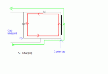
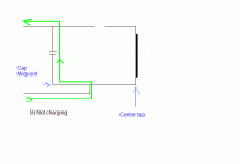
Just to try to make it even clearer what I meant before about the grounding issue, I have drawn two figures showing what you all know already. I show the PSU for one rail only, to simplify. Load current is shown in green and charge current in red.
Case A is when the diode is forward conducting and charges the caps. In this case there is both load current and charge current flowing in the circuit.
Case A is when the diode is forward conducting and charges the caps. In this case there is both load current and charge current flowing in the circuit.
Attachments
Case B is when the diode is reverse biased and no charging takes place. In this case the loop through the winding can be considered as broken, so the load current flows back to the caps instead of the transformer. This is usally the case for most of the time. I omitted the diode in this case to emphasise that the loop is broken.
It is clear then that there is always current flowing through the cap midpoint, but only sometims is there current flowing through the transformer center tap. So to answer Mikes question "what happens at the center tap", most of the time nothing happens at the center tap.
I should also point out that i deliberately returned the load current to a point between the cap midpoint and the center tap in order not to have a preconceived notion of where it should be returned. As soon as we choose either point as our return point, then all current will pass through that point because of our decision.
Attachments
Christer said:
I should also point out that i deliberately returned the load current to a point between the cap midpoint and the center tap in order not to have a preconceived notion of where it should be returned. As soon as we choose either point as our return point, then all current will pass through that point because of our decision.
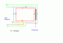
Preconceived or not, the amplifier return should be attached to the capacitor as short as possible. The AC voltage drop of the charging ripple current on the wire marked yellow will be seen by the amplifier no matter how good the cap is. In fact, the better the cap (closer to AC short), the worse it gets.
It makes no sense first paying obscene amounts of money for first class low-inductance, low-resistance capacitors and then making sure that one doesn't get the advantages.
Gerhard
Attachments
Hi Christer,
thanks for your two sketches.
They help illustrate two points.
1. the smoothing caps see a reversal of current. The ripple current. Design for it. It heats up capacitors (all types including non-polar).
2. the location of the load return and the load supply should both be from the best positions. Your diagram shows the load supplied from the cap. Is this best? or is it better from somewhere else?
The return is shown on a leg "from" the centre tap between the windings AND on a leg "from" the 0v common between the smoothing caps (the other half of the winding and cap are omitted as Christer explained). Is this the best place for it? or is there better?
I will put my money on the answer to 2. being Christer has already put the power supply ground in the best place, using a leg to separate it from the smoothing cap centre and on a leg separating it from the centre tap.
When Christer adds the lower half to these charging and discharging sketches, I think it will become obvious that the best place for the grounding side turns out to be Christer's unbiased first position (as shown).
Where do we go to answer 1. supply tapping point?
gerhard said:
Preconceived or not, the amplifier return should be attached to the capacitor as short as possible. The AC voltage drop of the charging ripple current on the wire marked yellow will be seen by the amplifier no matter how good the cap is. In fact, the better the cap (closer to AC short), the worse it gets.
I agree with you, and I am sorry if I was unclear. I just meant that as soon as we make the decision we have affected the result. Hence we should have a neutral approach when finding out where the currents flow. As soon as we have decided on a return point then all currents will flow thrugh that point, making the argument of where the currents flow pointless. After finding out where the currents flow, we can choose a suitable return point, and there I agree with you that the cap midpoint (or slightly off that point) is preferred.
This all stems from a claim that the transformer center tap should be a better ground return point because that is where all currents return. It is is clearly not the case that all currents return there, except during charging phases, and the figures were only meant to clarify this.
Andrew, I think you misunderstood me slightly. I do not say that the ground return should be where I drew it, between the caps and the transformer. I deliberately choose that position in the sketches to show clearly where currents flow. If we choose for instance to return the load current to the center tap, then of course all currents must flow through that point. But then claiming that the center tap is the best point because all currents return there is a circular argument since we forced them to return there by choosing the center tap in the first place. The same argument goes if we instead choose the cap midpoint. Hence, I used a point between them to avoid such circular argumentation.
The point of the exercise was to dismiss the earlier argument for choosing the center tap as return point.
I agree with Gerhard that the return point should be at the cap midpoint, or rather slightly off as described by Self and others.
The point of the exercise was to dismiss the earlier argument for choosing the center tap as return point.
I agree with Gerhard that the return point should be at the cap midpoint, or rather slightly off as described by Self and others.
Christer said:
I agree with you, and I am sorry if I was unclear. I just meant that as soon as we make the decision we have affected the result. Hence we should have a neutral approach when finding out where the currents flow. As soon as we have decided on a return point then all currents will flow thrugh that point, making the argument of where the currents flow pointless. After finding out where the currents flow, we can choose a suitable return point, and there I agree with you that the cap midpoint (or slightly off that point) is preferred.
This all stems from a claim that the transformer center tap should be a better ground return point because that is where all currents return. It is is clearly not the case that all currents return there, except during charging phases, and the figures were only meant to clarify this.
Christer,
your argument here completely ignores the case when one supply rail is sending a different current to the load compared to the other supply rail.
This situation applies when ever the speaker (amplfier load) is taking current and also applies if the quiescent current in the two supply rails is unequal.
If you look at the dual polarity case and analyse where the currents go when ONE rail is supplying zero current you will see that the speaker current flows through the leg entering the centre tap. (that's why I did my diagram with all those letters and numbers on it. It makes it easy to describe the route/s the currents are taking).
you made it quite clear to all that you did not wish to pre-empt the decision for "best" location. A good stance to take. I then offered my opinion explaining that NEITHER the centre tap NOR the cap common are the "best" place.
The main reason for my guessing where NOT to put the audio ground is that BOTh these locations carry the high charging pulses and these current pulses create voltages. If you try to place multiple connections on EITHER of these routes you will pick up different voltages. That is the buzzing one gets when trying to tap into the smoothing cap common plate and use this as a distributed audio ground.
is a very important phrase that happens to fit my argument.or rather slightly off
AndrewT said:
Christer,
your argument here completely ignores the case when one supply rail is sending a different current to the load compared to the other supply rail.
This situation applies when ever the speaker (amplfier load) is taking current and also applies if the quiescent current in the two supply rails is unequal.
If you look at the dual polarity case and analyse where the currents go when ONE rail is supplying zero current you will see that the speaker current flows through the leg entering the centre tap. (that's why I did my diagram with all those letters and numbers on it. It makes it easy to describe the route/s the currents are taking).
I disagree with you. Do I really have to draw the full figures with dual rails?
AndrewT said:yes
draw it if need be.
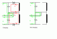
OK, here we go.
I ignore the cases where only one rail is charging, but that should be straightforward from these two cases.
Then you have to sum currents, of course, to find out in which direction current is actually flowing in the varios ground leads.
Attachments
Hi,
taking the simpler (not charging) diagram first.
If the two rail currents are equal (I1=I2) then the current in the middle wire is zero.
That was your first observation (no current in the leg to the ground).
That also means no current in the horizontal wire from cap common to the ground wire. This is the situation that was referred to earlier by others.
Now look at the situation when the two rail currents are not equal.
I1 does not cancel with I2.
That means that there is current flowing in the middle wire.
This current is exactly equal to the difference between the two rail currents.
Now. let's consider what this unbalanced current is.
The voltage amplifier draws quiescent current. often these quiescent currents are very similar on the two rails, but they do not have to be identical, in fact it would be very difficult to design them to be identical. However, these quiescent currents are essentially DC currents and will not modulate the voltage on the rails.
The next current drawn from the rails is the output bias. This again is a DC current.
Finally we arrive at the current that we really need, the load current. Since we are dealing with dual polarity supplies and a push pull amplifier, this next part applies exclusively to this case.
The load current is supplied by one half of the output stage. the other half cuts off. This load current is exactly equal to the increase in one rail current plus the decrease in the other rail current (Iload=I1' -I2'). The amplifier will move out of it's ClassA range and become ClassAB. the current in the lower rail will go to virtually zero and the current in the upper rail will be very slightly higher than the load current. Now let's trace the route that this load current takes.
I'll use my numbers and letters to make it easier to follow:load current comes out of the amp and entersthe load, comes back out of the load and goes to D2-B-8-7-6-[amplifier+ve] then back to amp output.
When the signal reverses to the other half waveform the top half of the amplifier cuts off and the lower half of the output stage sinks the load current. The new route is D2-B-8-9-10-[amplifier -ve].
The current we are dealing with here is audio frequency and is relatively smoothly changing (upto high audio frequencies). That implies that the voltage drop in the leg B-8 is a smoothly changing voltage in phase with the audio output.
Now let's go to the charging version of the circuit.
I2 is approximately equal to I1 when the amp is idling. and this results in I3~=I4 when idling.
the current in the middle horizontal wire between the smoothing caps and the centre tap is I3-I4 and is approximately zero. The voltage drop in this middle wire due to charging currents is approximately zero.
The charging currents are going from the top diode down through both caps through the second diode and back up through both windings. That is equivalent to the route 1-2-3-4-5-6-7-8-9-10-11-12-13-14-15-16-1. no charging current in 16-A and no charging current in 8-B. But I think it is important that you should note that the voltage drops in 7-8 and 8-9 as well as the two wires above and below 16 are suffering from the voltage variations caused by the charging currents.
Let's add in the load current. Fortunately I don't have to repeat myself, it is identical to the earlier not charging case. The two routes act independaently of each other except that a partial cancellation of charge into and load current out of each of the capacitors in turn when charge co-incides with draw (in that capacitor). The capacitor has a tiny bit less ripple when the draw and charge coincide. But only for that short period of charge (about 5 to 10% of the waveform period).
I don't think I have been fully exhaustive here but hopefully enough to get on with.
Andrew,
you are really trying hard to make things more complex and mysterious than they are. It doesn't really matter if the load is an amp or whatever. Just look att how the currents flow and apply Kirchoff.
I really don't know what you were trying to say with your most recent post, but as far as I can see, what you said conforms well with my figures. Does that mean you agree with me? Or what were you trying to say?
Christer said:post 83: .......It is clear then that there is always current flowing through the cap midpoint, but only sometims is there current flowing through the transformer center tap. So to answer Mikes question "what happens at the center tap", most of the time nothing happens at the center tap.
Christer said:post86......... I agree with you that the cap midpoint (or slightly off that point) is preferred.
This all stems from a claim that the transformer center tap should be a better ground return point because that is where all currents return. It is is clearly not the case that all currents return there, except during charging phases, and the figures were only meant to clarify this.
These statements show we are on different planets.
I am not trying to make it mysterious.
I am trying to explain it simply (but unfortunately far too long) to see where our views/understanding diverge.
The really big point I am trying to make is that at 16 and at 8 there are large charging pulses that leak into the speaker output if either of them are chosen as an audio ground.
AndrewT said:
The really big point I am trying to make is that at 16 and at 8 there are large charging pulses that leak into the speaker output if either of them are chosen as an audio ground.
Then why didn't you just say that?
I agree with that, and that is the reason that Self and many others recommend to have the return point slightly off from the cap midpoint. But note, slightly off, not far away. That is however merely a small adjustment of the fundamental choice of the cap midpoint. I thought we were still discussing the transformer center tap and its (un)suitability as a return point.
AndrewT said:Hi Gerhard,
I think you are applying the wrong logic.
The result you get is then flawed.
I do not agree with your conclusion.
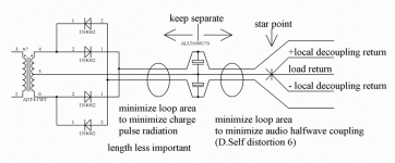
I think it should look this way:
Attachments
kvholio said:
By keeping the ground-traces, +ve and -ve close together.
In the few designs i've made they always end up at the center of the pcb, not at the extremities.
This also offers the advantage of having short connections for local smoothing/decoupling caps.
In practice , most of the times this means you have to turn the DRAWN schematic inside-out, not simply "copy" it to the pcb.
Klaas
This is intersting
could you show some layouts to teach 'copyists' like me?
gerhard said:
I think it should look this way:
Agree, but with the star point as close as possible to the cap midpoint, but not exactly at the midpoint. That is, the lead between caps and star ground should be as short as possible but not zero length.
Hi Christer,
have a look at psu.zip
A=connection to centre tap, this is very short 20mm to 50mm.
B=connection to cap common, this is very short 20mm to 50mm.
Join A & B and this junction becomes the start of the audio ground.
6-5-4 and 10-11-12 are twisted together, these are very short, 40mm to 60mm.
1-2-3 and 15-14-13 are twisted together, these are short 50mm to 100mm
All these connections fit with "keep it compact" and "small loop area".
Keeping them short fits with the low impedance (inductance + resistance) requirement.
But importantly, the audio ground is Neither the centre tap NOR the smoothing cap common.
- Status
- This old topic is closed. If you want to reopen this topic, contact a moderator using the "Report Post" button.
- Home
- Amplifiers
- Solid State
- Bob Cordell Interview: Power Supplies
