Hi Gerhard,
I like your diagram.
It summarises many of the requirements for a quiet audio ground.
I do not think the + & - local decoupling should be brought back separately to the audio ground (star). I think the+ &- should be coupled very close to the current usage point and then the common return brought to the audio ground. This is to allow the bypass to be effective at the high frequencies that the bypass is supposed to work at.
I have found that your point 5 (centre tap connection) can be taken straight to the audio ground and miss out the tie-in to the cap common. I think this works because there are no charging currents in the centre tap to star connection.
But I think that, if done this way, then the additional requirement for short becomes more important. Overall, I believe the ground is quieter if the centre tap to cap common is not made as a direct connection, but I am unsure how to prove whether this is a valid observation.
Christer said:
Agree, but with the star point as close as possible to the cap midpoint, but not exactly at the midpoint. That is, the lead between caps and star ground should be as short as possible but not zero length.
No, the caps center via a short wire to the star point. The location of the star point is usually
dictated by the amplifier's local decoupling and is therefore a stability issue.
The FETs/BIPs discussed in the other B.C.I thread still work at 30 to 300 MHz.
A 100 nF cap is of no use if it is attached with 15 cm of wire.
100 nF 1206 SMD is inductive above 7 MHz already without any leads.
Gerhard
gerhard said:
No, the caps center via a short wire to the star point. The location of the star point is usually
dictated by the amplifier's local decoupling and is therefore a stability issue.
The FETs/BIPs discussed in the other B.C.I thread still work at 30 to 300 MHz.
A 100 nF cap is of no use if it is attached with 15 cm of wire.
100 nF 1206 SMD is inductive above 7 MHz already without any leads.
Gerhard
Let's see, you want the star point at the amp itself? I actually missed that you had drawn the local decoupling to the star point in your diagram. In that case, yes, you must probably have the star point at the amp. However, I think the more usual solution is to connect the local OPS decoupling to the load return at the amp, rather than directly to the star point. In that case the star point can be located where I suggested. This comes back to the previous discussion on taking everything to the star point or closing some loops locally.
lm3875 with bigger ps-caps:
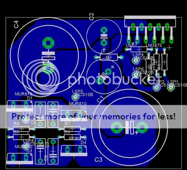
le monstre with substitute-parts:

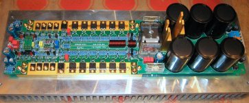
ksa-50 with integrated output-stage and 4x10.000 uF ps-caps.
Made to fit particular heatsink.
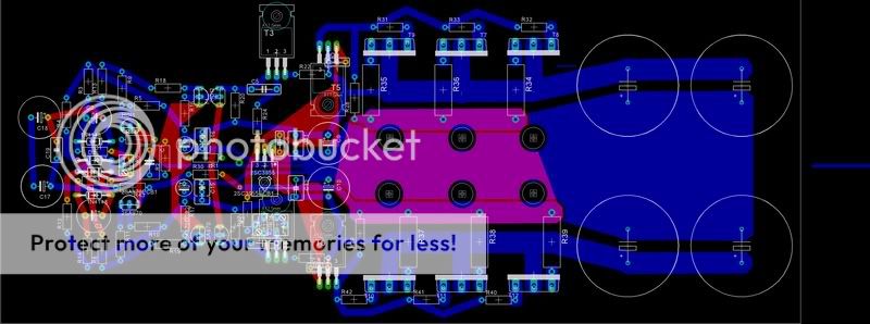
Note: in my opinion there are serious flaws in these designs, some of them are clear to me now thanks to this thread and this forum.
Only amp that i actually got built using my own pcb's is the le monstre.
Klaas
le monstre with substitute-parts:
ksa-50 with integrated output-stage and 4x10.000 uF ps-caps.
Made to fit particular heatsink.
Note: in my opinion there are serious flaws in these designs, some of them are clear to me now thanks to this thread and this forum.
Only amp that i actually got built using my own pcb's is the le monstre.
Klaas
Well, I was going to weigh in with what I was thinking but there's at least a half a dozen new detailed posts I want to make sure I understand before I do.
I do believe that you have to separate the circuit operating currents and the audio signal current paths in the discussion because they actually function independently unless they get in each others way.
Anyway it's to late now so I'll try to find time in the morning.
Regards, Mike.
I do believe that you have to separate the circuit operating currents and the audio signal current paths in the discussion because they actually function independently unless they get in each others way.
Anyway it's to late now so I'll try to find time in the morning.
Regards, Mike.
I think you are right.MikeBettinger said:I do believe that you have to separate the circuit operating currents and the audio signal current paths in the discussion because they actually function independently unless they get in each others way.
I would add the amplifier power circuit (high current) and Safety Earth to the list.
Mains Safety Earth, Rectifier/smoothing, PCB/speaker power, Signal/NFB
This fits the philosophy of closing the local loops.
Hi all
Rather than use additional transformers to add the extra volts to the power rails, why not use the voltage-doubling rectifier method?
I've used this on several amps now. As the load needed by the VAS etc is only a few tens of mA relatively small caps only are needed. A linear regulator then can drop the excess volts and provide a highly stable supply to the critical input stages. Only needs four smallish caps and a pair of HV diodes (1N4007's) per side, plus decent regulator tranny per side.
I agree with the comment that separate compartment regular transformers give better isolation than the toroids.
cheers
John
So, back in post 59 Andrew disagreed, as he had before, to my assertion that there should be one main ground and that it should be located at the center tap of the power transformer. Several posts followed discussing what was actually occurring at this circuit node with the outcome being, and I’m summarizing here, that as far as the power circulating through the circuitry there is little returning. This I agree with since I can remove all connections to ground in my amps (bipolar, symmetrical layout) and nothing changes as far as operating points. Audibly, music squeaks through when the speaker load is included but without the reference to ground at the input there is a pronounced hum.
His diagram highlighted to me that when I think of ground I only think in terms of what IS actually returned to the center tap and more or less block out the circuit biasing. My thought is that, most of this biasing is stable with the currents in a given circuit loop being at least 10X whatever the signal demands on the circuit might be, so these variations are fairly benign ith the exception of the output stage, but even here the biasing stays constant and any variations in power through the stage pass through the load to ground. This last point is what I consider important: when current is being supplied to the speaker it originates from either polarity supply and follows a path through the outputs, the speaker, then back to the secondary return for either secondary. So in reality there is current flowing into the center tap whenever there is current through the speaker.
With this in mind if we agree as Andrew has stated that we close the charging loop by bringing the filter caps back to the center tap, the output loop from the rectifiers through the output stage, and the load needs to complete its loop there as well. If, as suggested, we instead run a short wire to a power stage, speaker return, Zobel, etc. ground, and then maybe another short run to an input signal loop / star, I have found you run into trouble.
The first wire separating the speaker / power stage return creates a noisy reference due to the return current (which in the case of a speaker can be quite formidable; any further connections down the line are affected by this. A very effective feedback path is created for the speaker currents, bypass cap signals, regulator returns right back into the input and feedback signals.
The reason it is important to be right at the transformer is that is where the secondary windings create a zero reference, which in a perfect world creates THE quiet ground we all search for… (In reality, the balance between the secondaries and the transformer nonlinearities need to be managed, but it is still the best ground you have to work with).
In my amps I dig into the transformers and bring the coil wires out separately and join them at the central ground, not allowing the positive or negative loops to mix. There is no possibility of unequal currents causing problems because the +/- loops are completely separate. (within the transformers limitations)
I've tried to summarize this as best as I can, although it makes perfect sense to me , I'm sure my mastery of words demands much to the imagination. So it goes for the demands of the holiday weekend.
Regards, Mike.
Hi Mike,
I think we nearly agree.
I suggest that the charging loop should be short and low loop area. This requires that all the wires be short in that loop.
It turns out that the centre tap is usually two wires (i.e. separate secondaries) soldered to a common earth tag.
Your suggestion is almost identical. Can I assume you use separate earth tags?
If A is connected to B with no wire extensions then the link 16-A in my diagram is the little bit of earth tag from the soldered joint to the perimeter of the ring around the bolt hole.
The crucial part for me is the the charging circuit comes in to the centre tap through one wire onto the end of the earth tag and back out again through the other secondary. BUT the charging circuit has NOT used the common connection up to the bolt. That little bit carries speaker current (plus unbalanced rail currents).
Can you try to explain paras 3 & 4 again for me? I have a picture of what I think you mean but before saying either way, I would like to be sure.
MikeBettinger said:
So in reality there is current flowing into the center tap whenever there is current through the speaker.
No, only when the caps are charging. This is the point I have been trying to make all the time. Whenever the caps are not charging, the diodes are reverse biased so the current loops through the windings, and hence through the center tap, are effectively broken. However, I am sure you know this too, so we must be seriously misunderstanding each other somehow.
In my amps I dig into the transformers and bring the coil wires out separately and join them at the central ground, not allowing the positive or negative loops to mix. There is no possibility of unequal currents causing problems because the +/- loops are completely separate. (within the transformers limitations)
This sounds like something we can agree on. Besides, I have never understood why people use transformers with center taps anyway. I don't even think I have ever seen one, but maybe they are common in some countries, for whatever reason.

Gentlemen, the discussion on Upupa's beautiful amplifiers deserves a thread on its own so it has been moved to "Pavel Dudek's (Upupa Epops) amplifiers", which is to be found here:
http://www.diyaudio.com/forums/showthread.php?s=&threadid=28683&perpage=10&pagenumber=1
Enjoy!
Regards,
Milan
Christer said:
No, only when the caps are charging. This is the point I have been trying to make all the time. Whenever the caps are not charging, the diodes are reverse biased so the current loops through the windings, and hence through the center tap, are effectively broken. However, I am sure you know this too, so we must be seriously misunderstanding each other somehow.
This sounds like something we can agree on. Besides, I have never understood why people use transformers with center taps anyway. I don't even think I have ever seen one, but maybe they are common in some countries, for whatever reason.
We have a fundamental disagreement here in that I have found that in my amps (as described) that the flow of power is a loop that starts at the rectifier output, flows through the output transistors, through the speaker and returns back into the secondary to complete the loop. The filters are there to smooth out the power and act as a source during dead time and to help absorb reactive energy reflected from the load. The capacitors are not actually in the signal path as far as the power output stage is concerned. This is where the difference between what the ground is doing (reference or current source) comes into play.
You can create a virtual ground without a center tap and, I know it works when powering low level circuitry because, as I stated, the ground is only used as a reference, and I'm assuming that you could build a power amp this way and force the return currents backwards through the filters, although I have not tried this, having always used the center tap, I’m sure it would work. but why use it in this application?
It would place the sound of the amp squarely on the quality of the caps and it would inseparably inter mix the charging currents with the load currents.
Implementation wise, by running the return currents back to the caps rather than the centertap a voltage is developed across whatever wire runs from the filters to the centertap. This is the source of the unintended feedback that I mentioned in paragraph 4.
If you think about a tube power amp with a positive-only supply to the output stage; the power flows from the supply through the transformer load the output tubes and is returned to the ground side of the supply completing the loop. A push pull amp that uses a +/- supply also needs to close this loop, only it has two separate loops.
Regards, Mike.
MikeBettinger said:One other thought. Think of the supply as two +/- DC sources without charging currents, rectifiers or filter caps, only a +/- DC potential with a center tap. Where does the current flow?
Regards, Mike.
That is a totally different situation. I am really starting to wonder if you actually even disagree with the figures I posted earlier? If so, we really have a fundamental disagreement of a most puzzling type.
Anyhow, since you seem to prefer not to have a center tap at all if there is a choice, we probably agree on that case at least.
Christer said:
That is a totally different situation. I am really starting to wonder if you actually even disagree with the figures I posted earlier? If so, we really have a fundamental disagreement of a most puzzling type.
Anyhow, since you seem to prefer not to have a center tap at all if there is a choice, we probably agree on that case at least.
I must not be being very clear
 What I'm talking about is needing a center tap!!! I don't know where the disconnect is.
 I don't have time now to sort it out since I'm getting ready to leave for the week. Going for LabView training in NC. If I can manage a internet connection while I'm away I can try. Did I lose everyone?
Regards, Mike.
Mike,
Let's just conclude that either we have some fundamental disagreement or, more probably, we misunderstand each other severely. So let's end the discussion here. It is not really important to me to sort this out and nobody else seems interested in the discussion either.
Let's just conclude that either we have some fundamental disagreement or, more probably, we misunderstand each other severely. So let's end the discussion here. It is not really important to me to sort this out and nobody else seems interested in the discussion either.
john_ellis said:Hi all
Rather than use additional transformers to add the extra volts to the power rails, why not use the voltage-doubling rectifier method?
I've used this on several amps now. As the load needed by the VAS etc is only a few tens of mA relatively small caps only are needed. A linear regulator then can drop the excess volts and provide a highly stable supply to the critical input stages. Only needs four smallish caps and a pair of HV diodes (1N4007's) per side, plus decent regulator tranny per side.
I agree with the comment that separate compartment regular transformers give better isolation than the toroids.
cheers
John
I agree, john, using voltage doublers should work perfectly fine, as the currents drawn by the VAS etc are rather small. Doubling gives you quite a bit more voltage than you need, though, so you'll burn a little power in the down regulators. On the other hand, a 10-20 VA transformer with a pair of isolated secondaries is only a few dollars.
Bob
Bob Cordell said:.....so you'll burn a little power in the down regulators.......
Bob
The power dissipated may not be insignificant if the first stage of drivers i included...
Bob Cordell said:
On the other hand, a 10-20 VA transformer with a pair of isolated secondaries is only a few dollars.
EXACTLY !
I found transformer solution cheaper compared to electrolytic caps for doubling! These should be rather high value.
Adam
P.S.
A question:
Have anyone had any problems with double suplly rails at startup?
I assume small power regulated rails are charging slower at startup, so I've added some diodes so that early stages don't have lower voltage.
I am not sure if this is mandatory. Anyone?
- Status
- This old topic is closed. If you want to reopen this topic, contact a moderator using the "Report Post" button.
- Home
- Amplifiers
- Solid State
- Bob Cordell Interview: Power Supplies