Hi Bobc,
We agree on a major part of the argument and this
But, this
There are three wires coming together at the centre tap.
Two are connected internally to the respective secondaries and one is connected to the outside world. You have chosen to ignore the different duty that each of the three wires has to meet. I explained it and you have ignored and printed that instead.
Please be good enough to elucidate.
The centre tap transformer side wires will see charging pulses irrespective of how large the smoothing capacitors are (for a capacitor input PSU there must be capacitors present), but the supply rail currents become asymetrical as soon as any unbalance occurs whether it be due to quiescent current or output current and completely irrespective of frequency. It matters not a jot whether the output signal is 20kHz or 20Hz, once output current flows the rail currents ARE ASYMETRICAL.
Asymetrical current in the rails brings in your second closed loop i.e. smoothing caps to speaker return, and demands that current flows from speaker return around the loop to either the upper or lower smoothing capacitor and partially discharges it. Notice that last "or", speaker current will discharge one or other polarity on each alternate half cycle.
don't bother with the "in a sense".You and Mike are both right in a sense.
We agree on a major part of the argument and this
confirms that you are in agreement about this part of the current flows during the charging cycle and during the output current cycle.Secondly, it is very imporatnt to recognize that there are two loops at work. One loop involves the center tap and the reservoir capacitors. It involves current pulses at twice the a.c. line rate. The second loop involves the speaker return and the reservoir capacitors. It involves current pulses from the Class-AB output stage.
But, this
is completely misleading.But the center tap current only flows in pulses at twice the ac line frequency.
There are three wires coming together at the centre tap.
Two are connected internally to the respective secondaries and one is connected to the outside world. You have chosen to ignore the different duty that each of the three wires has to meet. I explained it and you have ignored and printed that instead.
Please be good enough to elucidate.
I am not sure that this "separation" of capacitors is NECESSARY, but it may offer an improvement by separating the charging pulses from the audio currents.These two loops can be largely separated at ac by devoting two sets of reservoir capacitors, one to rectification and located near the transformer and rectifiers, and the second devoted to the amplifier output and located near the output transistors. The junctions of these two sets of capacitots each form a star where the relevant a.c. pulses are at least partially resolved locally. These two star junctions are connected together as part of a star-on-star topology. The rail lines connecting the two sets of capacitors can have some small resistance in them to force the current pulses to circulate locally.
I am even less sure that this is logical.First, the center tap is very important to the extent that the filter caps are not infinitely huge. They stabilize the rail voltages with respect to ground during the asymmetrical currents that do in fact flow at low frequencies
The centre tap transformer side wires will see charging pulses irrespective of how large the smoothing capacitors are (for a capacitor input PSU there must be capacitors present), but the supply rail currents become asymetrical as soon as any unbalance occurs whether it be due to quiescent current or output current and completely irrespective of frequency. It matters not a jot whether the output signal is 20kHz or 20Hz, once output current flows the rail currents ARE ASYMETRICAL.
Asymetrical current in the rails brings in your second closed loop i.e. smoothing caps to speaker return, and demands that current flows from speaker return around the loop to either the upper or lower smoothing capacitor and partially discharges it. Notice that last "or", speaker current will discharge one or other polarity on each alternate half cycle.
AndrewT said:Hi Bobc,don't bother with the "in a sense".
We agree on a major part of the argument and this confirms that you are in agreement about this part of the current flows during the charging cycle and during the output current cycle.
But, this is completely misleading.
There are three wires coming together at the centre tap.
Two are connected internally to the respective secondaries and one is connected to the outside world. You have chosen to ignore the different duty that each of the three wires has to meet. I explained it and you have ignored and printed that instead.
Please be good enough to elucidate. I am not sure that this "separation" of capacitors is NECESSARY, but it may offer an improvement by separating the charging pulses from the audio currents. I am even less sure that this is logical.
The centre tap transformer side wires will see charging pulses irrespective of how large the smoothing capacitors are (for a capacitor input PSU there must be capacitors present), but the supply rail currents become asymetrical as soon as any unbalance occurs whether it be due to quiescent current or output current and completely irrespective of frequency. It matters not a jot whether the output signal is 20kHz or 20Hz, once output current flows the rail currents ARE ASYMETRICAL.
Asymetrical current in the rails brings in your second closed loop i.e. smoothing caps to speaker return, and demands that current flows from speaker return around the loop to either the upper or lower smoothing capacitor and partially discharges it. Notice that last "or", speaker current will discharge one or other polarity on each alternate half cycle.
Andrew, I think it is my perogative to assume that we are using a conventional center-tapped transformer with one wire that comes out and goes to the common junction of the reservoir capacitors. All I am talking about is the importance of that wire and the nature of the current flowing through it. Only pulses flow through that wire when the diodes in the bridge rectifier are conducting, and the average current in that single wire is an amount that is needed to counter the asymmetry of the rail currents, whether that asymmetry is due to d.c. imbalance in circuit drain or a.c. going to drive the loudspeakers.
I don't think that anything I said is misleading or hard to understand, and I frankly don't think there is a lot of disagreement overall here.
Cheers,
Bob
Hi Bobc,
To me and I suspect most readers, "twice the ac line frequency" means mains line frequency.
Are you saying that your phrase meant audio frequency?
As far as I can ascertain and I think Mike agrees with me, mains AC line frequency pulses (the charging pulses) do not flow in the single wire from the centre tap to the exterior world of the transformer. The charging pulses (at twice mains AC line frequency) flow in the two wires that internally connect the centre tap to the secondaries.
It seems obvious to the three of us that this is the case, but it does not appear to a number of contributors to this or many other threads that this is the case.
If we can agree this, then maybe the others will see the sense in this argument and gradually, or more quickly, they too will come on board.
I quote your phrase again.But the center tap current only flows in pulses at twice the ac line frequency.
To me and I suspect most readers, "twice the ac line frequency" means mains line frequency.
Are you saying that your phrase meant audio frequency?
As far as I can ascertain and I think Mike agrees with me, mains AC line frequency pulses (the charging pulses) do not flow in the single wire from the centre tap to the exterior world of the transformer. The charging pulses (at twice mains AC line frequency) flow in the two wires that internally connect the centre tap to the secondaries.
It seems obvious to the three of us that this is the case, but it does not appear to a number of contributors to this or many other threads that this is the case.
If we can agree this, then maybe the others will see the sense in this argument and gradually, or more quickly, they too will come on board.
I am not sure this applies. Give me time to think this one through.Only pulses flow through that wire when the diodes in the bridge rectifier are conducting
MikeBettinger said:Interesting assessment. My point was simple and I was trying to present it in plain English for the people asking how to ground their amplifiers and I might add based on many practical applications.
Why interesting? If somebody makes an interesting claim, attempts to motivate the claim by an argument and also seems to have a fair understanding of what goes on, then if the argument appears to be wrong or confusing it would rather be interesting if nobody reacted. Don't you think?
In this case both Jan, Bob, Gerhard and I protested against something you claimed, since it seemed to violate elementary electricity theory. I don't think any of us really thought you meant it that way, so our protests were of course intended to try getting a clarification about what you actually meant, since this seemingly erroneous claim seemed to be vital to you argument for using the center tap as ground point.
The claim that caused the problem was that the speaker current always returns to the center tap. Our protest was that it only does so when the filter caps are charging, and otherwise it returns to the filter caps. I have still not seen any attempt from you to change your standpoint here or trying to tell us that you didn't mean that. In fact, it still seems (to me at least) as if you have not understood what we were asking.
Please note that I, and most surely also the other three, protested because we were interested in your claim and wanted to understand you argument. Hence we wanted to understand your argument correctly. If I had not been interested, I wouldn't have bothered about it at all. I have not argued with you with any malicious intent.
The concept that was returned repeatedly to me in the discussion was that no current returned through the centertap and that the return from the load followed a path through the filter caps to the opposite end of the secondaries.
During the periods between the charging phases, to be precise.
The load should be returned to the filter grounds.
That is a different issue, even if related. There are different opinions about where the central ground point should be. Neither of us were actually protesting against your claim that the center tap should be used as central ground point or trying to say it is a bad choice. We only protested against what seemed like an erroneous but vital part of your argument for that choice in an attempt to get a clarification of the argument.
The image posted in post 137 shows what I was attempting to say. Kirchoff's law applied.
But current flows only during charge phases, ie. when the AC magnitude is larger than the cap voltage plus a diode drop. This is the very issue being discussed all along. At all other times the diodes do not conduct, so the loops through the center tap and the windings can in practice be considered as broken, as I tried to illustrate in the figures in posts #82 , #83 and #92 Do you or do you not agree with that?
If you do not agree, then you must obviously mean something else than how many of us others understand you, since it would otherwise seem to violate Kirchoffs laws.
Maybe you are not considering instantaneous values of the current, but average values. However, that seems contradicted by other things you say.
I could go on trying to guess what what you actually mean, but why should I? Or anybody else? At least some us would surely make the wrong guess. If an argument is unclear, it would better be clarified by the person making it, than the readers trying to fix it up by themselves. That is the whole and simple issue.
I apologize for the prior blunt response, but think about how your comments might have been perceived.
I am sorry I have sounded rude too. I may have got somewhat irritated since you seemed to consistently either try to avoid the question or failing to understand what we were actually asking.
And please note, that this has never been about arguing against your opinion on where to ground things, but only about a part of your argument for your choice of ground point, in order to understand your motivation for the choice.
Hi Bobc,
having further thoughts.
When the average draw from the power rails is not even, then the two halves of the smoothing caps need different quantities of charge.
The upper or lower halves charge separately for part of the charging period.
During this phase of charging up the more drawn down caps, the centre tap to smoothing cap connection does indeed pass current to match the average rate of unequal drawdown.
Shame it's taken so long for this bit to sink in.
AndrewT said:Hi Bobc,
having further thoughts.
When the average draw from the power rails is not even, then the two halves of the smoothing caps need different quantities of charge.
The upper or lower halves charge separately for part of the charging period.
During this phase of charging up the more drawn down caps, the centre tap to smoothing cap connection does indeed pass current to match the average rate of unequal drawdown.
Shame it's taken so long for this bit to sink in.
Hi Andrew,
Exactly!
Cheers,
Bob
If i understand correctly, the length of the charging-periods will also differ.The upper or lower halves charge separately for part of the charging period.
The charging-period for the cap that sees the most current-draw, will be longer.
Is this correct ?
With kind regards,
Klaas
Hi,
my use of wording is almost certainly not accurate in that statement.
To expand a little and refer to an earlier discussion.
I said that the current in the upper half exactly cancelled the current in the lower half with the result that the current in the external leg of the centre tap is EXACTLY zero when the rail currents are equal.
What I have now realised is that the two halves of the smoothing caps can recharge at different rates to account for unequal draw from the supply rails.
When the differing recharging is happening it is probably a combination of slightly different currents in each polarity pulse, but also very marginally longer/shorter pulse time.
As an aside the difference current (through the centre tap) is going to be relatively much smaller than the total pulse current that runs through the secondaries.
The effect of this is that the voltage modulations induced in the external centre tap wire are of necessity going to be relatively smaller. This has implications for the dual secondary transformer that is converted to centre tap style by connecting the two secondaries together in series.
The risk of always overcomplicating an issue is failing to see a basic mechanism.
I enjoy analogies, two caps on a center tap make me think of riding a bicycle : two legs and also a center tap.
On a ship, two main engines are linked to the propellor shaft through a gearbox.
That way both engines do not influence eachother and the torque on the shaft remains constant.
A few thought of this mechanism well over 15 years ago, hence this reminder.
Mr. Cordell's Star-to-Star paragraph is more interesting, as has the rest of his 3 month appearance's been.
I hope we can suck him completely dry.
Hi Jacco,
your right on the interesting, the "star-to-star" is another way of saying close the local loops. That's what I have been promoting for months. It's also where I and others remind folk that the order of connecting the grounds together influence the outcome. Take care to avoid a distributed ground though, as done wrongly is guaranteed to increase hum and/or buzz.
Which part of the reminder were you referring me to? Pass, Ultima or yourself?
A scarse designer made amplifier models with a separate transformer and bridge rectifier for each rail because of believing in the merit of the thing so lengthy discussed here.
Including arguementation of the same length in the product brochure. (i've got a truckload of product brochures) Oldest one my nicotine brain can recall is late 1980s, it's all deja vu.
Including arguementation of the same length in the product brochure. (i've got a truckload of product brochures) Oldest one my nicotine brain can recall is late 1980s, it's all deja vu.
Interesting in how far we had strayed from my original intent. The main issue I was trying to address is one that Andrew and I had called a draw on in an earlier discussion and I still feel strongly about, which is where the main/star/reference ground in an amp/preamp should be located. The conversation branched into a number of sub topics which I attempted to keep intergrated (obviously confusing the heck out of everyone in the process), with the end result being where it was left.Christer said:
Why interesting?
The memorable part in your entrance into the discussion was the comments on the function of the centertap, which I felt compelled to respond to since it is fundamental to my location of choice for the main ground.
I think Andrews post (#159) very eloquently describes my understanding. I was was going to comment on his post, aligning what I had presented (in other words) with his description but I think it stands on it's own and I'm satified we're on the same page there (his discussion even highlighted the shift in currents based on the crossover from A to B, which I had not given any thought to) I believe we still have our differences in where to locate and implement the main ground but I'm not sure how to proceed discussing them.
Your comments are below and I'll attempt to address them
Christer said:Both Jan, Bob, Gerhard and I protested against something you claimed.
The claim that caused the problem was that the speaker current always returns to the center tap. Our protest was that it only does so when the filter caps are charging, and otherwise it returns to the filter caps. In fact, it still seems (to me at least) as if you have not understood what we were asking.
I understood what you were describing and my only response was to try and describe my point a bit differently so you might understand. I'll try again, once again conceptually.
My experience/understanding (and I could be wrong) here stems from the fact I view the purpose of the filter caps a bit differently. I look at them as support for smoothing the DC supply only, which starts at the rectifier outputs and returns to the centertap. Once we added in the rectifiers and the need to sustain the power the filters become necessary, but only to the extent that they are enabling a steady DC supply and return.
My approach is to keep this loop to this function only, connected between the rectifiers and the centertap.
The next important loop is the DC from the rectifier through the output transistor back, once again to the centertap. I don't see any other place it needs to go because the +/- supplies do not interact as far as the signal is concerned (with the exception of the crossover point interaction that Andrew describes). The current for the circuit biasing flows from negative supply through the circuitry and back into the positive terminal (exceptions previously noted)
The third loop of importance is the signal reference. And this needs to be as clean as possible or the input signal/ feedback is contaminated. Accomplishing this is the tough part, especially if either of the two return currents noted above are also circulating on their return paths to the centertap. Which is the basis of my approach to implementing (and where) the main ground. This is an extension of the above thoughts that only works if one accepts the premise as presented.
Christer said:There are different opinions about where the central ground point should be. Neither of us were actually protesting against your claim that the center tap should be used as central ground point or trying to say it is a bad choice. We only protested against what seemed like an erroneous but vital part of your argument for that choice in an attempt to get a clarification of the argument
But current flows only during charge phases, ie. when the AC magnitude is larger than the cap voltage plus a diode drop. This is the very issue being discussed all along. At all other times the diodes do not conduct, so the loops through the center tap and the windings can in practice be considered as broken.
I totally agree with your discussion of the charging currents and their timing, but feel that even when the diodes are not conducting the centertap is still sinking the return from the speaker and is still needed as the root source for the reference grounds.
My thoughts on this has germinated over many years after reading a description of the ideal ground as a unvarying potential that could source electrons without electrically changing. Every system needs this.
Hopefully this makes some sense. As part of my job I'm constantly describing technical concepts to mildly technical people, so I find that this is how I describe things. I also find this site a moving target as to what level the audience is on, it doesn't always work.
Regards, Mike.
Just to add a bit more fuel to the fire ")
Center tap current also flows when filter caps are not exactly equal in capacitance, or transformer winding sections are not exactly equal, but of course only during cap charging (at least one diode in the rectifier bridge must be conducting).
The whole point is to separate the charging currents (rectifier) from the discharging currents (amplifier), by making the common path the shortest possible. This is actually not that big a problem, but unfortunately, most of the common path is usually within the caps ithemselves where it can hardly be helped except by the choice of caps. This problem is greatly reduced by paralelling caps along 3 wires connecting center tap of transformer with ground of amplifier, + of the rectifier with + rail of the amplifier, and - of the rectifier with - rail of the amplifier, as the wire lengths between form PI filter sections with the caps.
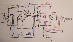
In my opinion, we are dealing with 3 current loops (picture below).
When the diode conducts, currents i1 and i2 flow. Current i1 is the charging current of capacitor C1 whereas current i2 is the current which flows directly from the transformer to the amplifier and the speaker. Both currents (i1&i2) return from B to A by the same path so the path must be kept as short as possible. This leads to the conclusion that the optimum design would be the one with only 1 ground star point!!
These 2 currents usually flow 10% (gainclone fans increase that time by up to 20% or more!) of the time of amplifier's operation, which is something that must not be overlooked. The rest of the time, current i3 flows and the capacitor C1 feeds the amplifier.
My two cents,
Milan
Attachments
moamps said:In my opinion, we are dealing with 3 current loops (picture below).
When the diode conducts, currents i1 and i2 flow. Current i1 is the charging current of capacitor C1 whereas current i2 is the current which flows directly from the transformer to the amplifier and the speaker. Both currents (i1&i2) return from B to A by the same path so the path must be kept as short as possible. This leads to the conclusion that the optimum design would be the one with only 1 ground star point!!
These 2 currents usually flow 10% (gainclone fans increase that time by up to 20% or more!) of the time of amplifier's operation, which is something that must not be overlooked. The rest of the time, current i3 flows and the capacitor C1 feeds the amplifier.
My two cents,
Milan
I agree with the one star ground point, but not really with the i3 current path. I'll make a diagram of my thoughts later and post.
Regards Mike.
ilimzn said:Just to add a bit more fuel to the fire
Center tap current also flows when filter caps are not exactly equal in capacitance, or transformer winding sections are not exactly equal, but of course only during cap charging (at least one diode in the rectifier bridge must be conducting).
The whole point is to separate the charging currents (rectifier) from the discharging currents (amplifier), by making the common path the shortest possible. This is actually not that big a problem, but unfortunately, most of the common path is usually within the caps ithemselves where it can hardly be helped except by the choice of caps. This problem is greatly reduced by paralelling caps along 3 wires connecting center tap of transformer with ground of amplifier, + of the rectifier with + rail of the amplifier, and - of the rectifier with - rail of the amplifier, as the wire lengths between form PI filter sections with the caps.
Agreed on the first part, parts are never perfect and you can hear imbalances in the secondaries. Bifilar windings are important.
The second part I'm having trouble visualizing, but it's been a tough week (that's finally over). I'll try again later.
Mike.
AndrewT said:Hi Bobc, I quote your phrase again.
As far as I can ascertain and I think Mike agrees with me, mains AC line frequency pulses (the charging pulses) do not flow in the single wire from the centre tap to the exterior world of the transformer. The charging pulses (at twice mains AC line frequency) flow in the two wires that internally connect the centre tap to the secondaries.
Agreed, as I mentioned going in and bringing the CT windings out separately to connect independently to the star/main ground. It defines these loops independently.
Regards, Mike
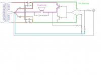
Here's a diagram. I'm not saying I'm right or wrong, it's more that I've had real good performance and It makes sense to me based on the evolution of the approach and the sonic performance. I'm very aware of the other approaches posted on the site, I'm drawn to anything layout related.
Feel free to poke holes in it.
Regards, Mike
Feel free to poke holes in it.
Regards, Mike
Attachments
MikeBettinger said:Here's a diagram. I'm not saying I'm right or wrong, it's more that I've had real good performance and It makes sense to me based on the evolution of the approach and the sonic performance. I'm very aware of the other approaches posted on the site, I'm drawn to anything layout related.
Feel free to poke holes in it.
Regards, Mike
It seems to me you forgot about wires from diodes to capacitors...
Hi Moamps.
i1 and i3 routes I agree with.
I see two alternatives for i2 route.
a). as you have drawn.
b). from cap C1 to amp+ve, to spkr, from spkr, to A, up thro' secondary, to bridge, downthrough diode, to C1. (this route does not need to go through B.
Either route works electrically.
Our discussion is whether a) or b) or something else, performs better for audio.
- Status
- This old topic is closed. If you want to reopen this topic, contact a moderator using the "Report Post" button.
- Home
- Amplifiers
- Solid State
- Bob Cordell Interview: Power Supplies