Bob,
Thank you for the summary!
Rather than quoting it verbatim, let me just make two remarks, also addressed at Brian.
The 'low fb' view with the fb factor 1/(ab-1) (if I got that right without looking back to the page), as you say, shows that the fb 'automagically' adjusts to the error. With EF gain of 0.95 or so, it is just a bit positive. Brain maintains that when the EF gain would be 1.0000, the fb would be huge/infinite. On the contrary, I maintain that it is zero.
I have built several of these circuits. In one, I used a synthesized pfb gain block as mentioned by you. I also used an output stage with a nominal gain of > 1 (3 in this case). You can then use trimmers in various places to adjust for best null and/or balance and see what happens.
At that point, two things stood out:
- the error correction signal fed back approaches zero, which I interprete as a feedback of zero, and not infinite;
- if you turn your adjustments so the correction gain or forward loop gain becomes too big, sort of tuning the pfb part 'through +infinity to -infinity' , the distortion that was at a minimum starts to increase again, but flipped 180 degrees in phase, when looking at the THD analyzer waveform. I would have expected stability problems here, but this and other similar circuits invariably are very docile and almost refuse to oscillate.
It's too long ago for me to remember all the details from way back when, but this stuck in my mind.
The proto amp circuit I used for these tests is in the attachment, and is from my AES paper.
Jan Didden
Attachments
Re: Some summary views on EC
Which has been already illustrated here:
http://www.diyaudio.com/forums/showthread.php?postid=1282575#post1282575
Bob Cordell said:There are at least three valid ways of looking at Hawksford Error Correction (HEC).
[snip]
Which has been already illustrated here:
http://www.diyaudio.com/forums/showthread.php?postid=1282575#post1282575
Oh now look what you've done, Bob. You've set me back many pages of progress with Jan. He's again focussing on the signal at the input to the emitter followers and keeps mistaking this as evidence of low NFB. I was so close. 🙄 😎
Any chance of having a word with him?
Any chance of having a word with him?
traderbam said:Oh now look what you've done, Bob. You've set me back many pages of progress with Jan. He's again focussing on the signal at the input to the emitter followers and keeps mistaking this as evidence of low NFB. I was so close. 🙄 😎
Any chance of having a word with him?
I love to stir the pot 🙂.
Bob,
For your sins I am handing Jan over to you. At least until you undo the damage you have done.

If you don't agree with that then our differences lie right at the roots of physics and are probably irreconcilable.
For your sins I am handing Jan over to you. At least until you undo the damage you have done.
Among many!You are certainly one tough customer.
You know very well I have. Although I would forgive you for forgetting as it was over 9 months ago, burried somewhere in this tomb. You may recall I simulated the NFB loop gain and asked you for your bench measurements to compare. Did you have any? Well, in any case the THD reduction you did measure was explained by the NFB factor from the sim. I have done many simulations and algebra on your circuit and HEC.Second, I think you should do a bunch of SPICE runs, as I have, to investigate the behavior.
Feedforward is correction by cancellation. Feedback is correction by hunting for a stable, minimal error equilibrium.The error correction view does indeed work perfectly well, and is perfectly realizable, and SPICE has absolutely no problem with it. I can demonstrate that one gets the same distortion reduction whether the error is fed back or fed forward. I'm sure you are not going to quibble with the conventional view of true feedforward error correction.
If you don't agree with that then our differences lie right at the roots of physics and are probably irreconcilable.
The smidge is because the place you are measuring the PFB is coincident with the NFB loop, which is taming the PFB loops desire to oscillate. The gain of the NFB is very big...and is not related to small output errors. That's what I think I said. By the way, I don't look at these circuits as "good" or "evil", they are what they are. I leave those spiritual judgements to George Dubbya. 😀You seem obsessed with the evil of positive feedback, and are wrong in rejecting the last view. The last view states that one just needs a smidge of positive feedback (net) to get the gain of the EF to exactly where it needs to be.
Yes I do, thanks. 🙂The proof is in the pudding. These circuits really work, both in the real world and in simulation. SPICE is perfectly happy with them. In SPICE, they produce incredibly deep nulls (perhaps you prefer the term 100 dB minima?).
traderbam said:Bob,
Feedforward is correction by cancellation. Feedback is correction by hunting for a stable, minimal error equilibrium.
If you don't agree with that then our differences lie right at the roots of physics and are probably irreconcilable.
Hi Brian,
I guess then that our differences are indeed irreconcilable 🙂
I apologize for forgetting about your SPICE simulations. It was a long while ago.
Cheers,
Bob
Ok fine Bob.
But I want half the value of the house and I want the croquet set. You can keep your vacuum tubes and the lengerie I bought you for Christmas.

But I want half the value of the house and I want the croquet set. You can keep your vacuum tubes and the lengerie I bought you for Christmas.
traderbam said:Ok fine Bob.
But I want half the value of the house and I want the croquet set. You can keep your vacuum tubes and the lengerie I bought you for Christmas.
BTW, note that in my summary of the error correction view of HEC, I stated that I can derive the output stage error and either feed it back (HEC) or feed it forward, and get exactly the same distortion performance, including spectra. I expected you to challenge me on that. If I can do that, how can you continue to say that feeding back the error is not a valid or realizable view?
Cheers,
Bob
Bob,
I can't even spell lingerie. How do you expect me to understand your paper? I'll have to take a look and get back to you.
Brian
I can't even spell lingerie. How do you expect me to understand your paper? I'll have to take a look and get back to you.
Brian
traderbam said:Oh now look what you've done, Bob. You've set me back many pages of progress with Jan. He's again focussing on the signal at the input to the emitter followers and keeps mistaking this as evidence of low NFB. I was so close.
If it's any consolation, I think you're correct.
😎
Nelson Pass said:
If it's any consolation, I think you're correct.
😎
You're right: Brian has been set back many pages with Jan 🙂
Re: Some summary views on EC
Bob,
I must admit to be confused here.
Do you agree the block diagram in my post here does represent also the third case? Please correct me if I have left something vital out or introduced an equally damaging spurious part.
If that were not the case, we can take for the EF stage values of 0.95 for A and 1 for A'. True the correction signal values are indeed small, but this seems not to detract from the fact the equivalent loop gain as per the second viewpoint - negative feedback system with local positive feedback loop - is quite high upon "null" adjustment.
I fail to see in what sense this third approach is distinctive from the others, which we agree are different faces of the same beast, unless the particular values (almost unity gain) and context (output stage only) make it stand out in your oppinion, something that is perfectly legitimate stated this way.
Rodolfo
Bob Cordell said:......
The third view of HEC is the “low feedback” view. Here it is recognized that the emitter follower output stage needs a little bit of a gain boost to get its gain back to exactly unity. This can only be accomplished with a very slight bit of net positive feedback. 1/(1-AB) factor will have to come out to about 1.053 in this case. The amount of slight positive feedback is arrived at by what amounts to a bridge circuit, where a subtraction takes place between what is put into the output stage and what comes out of the output stage. This creates a very small residual amount of feedback that has a very small amount of loop gain that can be positive or negative feedback. In this case, it will usually be slightly positive as mentioned above.
The magic in this view of HEC is that the feedback factor is adaptive in that the error in the output stage adapts, or adjust the small amount of feedback needed to correct the incremental gain of the stage. The key here is to realize that the actual amount of correction that needs to be applied to the emitter follower output stage is quite small, so that only a very small amount of net feedback is necessary.
...
Bob,
I must admit to be confused here.
Do you agree the block diagram in my post here does represent also the third case? Please correct me if I have left something vital out or introduced an equally damaging spurious part.
If that were not the case, we can take for the EF stage values of 0.95 for A and 1 for A'. True the correction signal values are indeed small, but this seems not to detract from the fact the equivalent loop gain as per the second viewpoint - negative feedback system with local positive feedback loop - is quite high upon "null" adjustment.
I fail to see in what sense this third approach is distinctive from the others, which we agree are different faces of the same beast, unless the particular values (almost unity gain) and context (output stage only) make it stand out in your oppinion, something that is perfectly legitimate stated this way.
Rodolfo
Hi Bob,
I want to offer a slightly different perspective that I don't think contradicts your post above but better illustrates my point of view. First I want to offer a minor comment about your discussion, which is overall clear, however I wonder why you don't even mention distortion and put the emphais on the less than unity gain. I certainly understand that EC corrects both, however it just seems that the non-linear distortion should be the emphasis.
Anyway, let's assume an output stage gain of .95 and in my preferred implementation I would place a .95 resistive divider in the path to the diff amp from the input of the output stage. This prevents the EC from compensating for the slightly less than one gain of the output stage but retains the error correction for true non-linear distortion.
Now, let's for the moment assume a perfect distortionless gain of .95 output stage, then the output from the EC diff amp is zero and there is no feedback. I find this to be very different from traditional negative feedback which does not isolate the error from the signal. You, obviously know this seeing as you wrote the paper and I am just commenting for others.
I'm not disagreeing with what you wrote just offering another solution to clearly show this particular difference.
Pete B.
jcx said:I don't understand the abstract part - I could build very nearly the circuit shown in the big triangle, pot it and hand it to someone with instructions measure the gains I simmed for this circuit
I could then ask them to connect it around N as illustrated and ask for an explanation of reduced distortion at the output of N
would a 3rd year EE student be tempted to ascribe the distortion reduction to the "apparent, abstract, theoretical" gain they had just measured? - how about their Professor?
I think they would be just fine with it, as I am. However, it was you who claimed that positive feedback was not even taught anymore and implied that there was something wrong with it:
http://www.diyaudio.com/forums/showthread.php?s=&postid=1308335&highlight=#post1308335
Don't forget I pointed it out first which I only bring up because you act as if you need to educate us all:
http://www.diyaudio.com/forums/showthread.php?postid=1062575#post1062575
By the way, regeneration brings back wonderful memories, my Dad explained how regen receivers worked when I was about 8 years old. I actually built one as a kid.
So if we all looked inside the box, I might say isn't that interesting that it is built from unity gain diff amps, but it seems you would worry about the pfb (while the loop is open) and that it is not taught anymore, given your previous statements, LOL!
However, what I find odd is that you insist on chopping the design up in such a way that supports your abstract view of high pfb. Most designs will not function the same when you chop them in two, LOL! Don't you see this? You've altered the circuit to support your view.
Sorry, I don't enjoy this type of back and forth, and I don't have time for it. I don't disagree with your claims when you chop the circuit however we will probably have to agree to disagree about other points of view.
Let me ask you point blank, would you not use EC in a power amp design? And what sort of design would you come up with if the goal was ultra low distortion, or as low as possible?
Pete B.
PB2 said:
...
However, what I find odd is that you insist on chopping the design up in such a way that supports your abstract view of high pfb. Most designs will not function the same when you chop them in two, LOL! Don't you see this? You've altered the circuit to support your view.
how about I measure the high differential gain with the circuit "put back together"?
This sort of measurement is practically difficult in the real world but Spice makes it easy to see my "abstact, theoretical" differential gain:
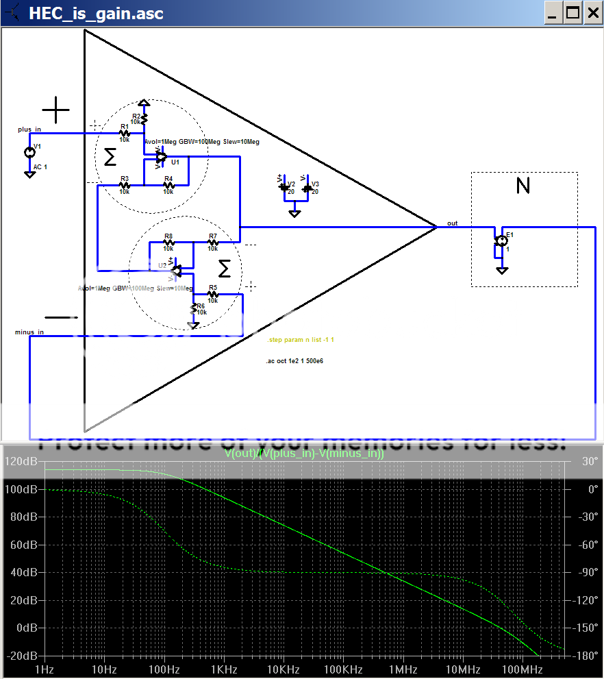
Did you miss Bob's comment that the "high gain" viewpoint is equally valid and therefore equally active and demonstrable when the EC circuit is working in full "EC" glory with internal node voltages that fit your sims of several pages ago with the "EC" heuristic explainations of this exact same circuit?
Let me ask you point blank, would you not use EC in a power amp design? And what sort of design would you come up with if the goal was ultra low distortion, or as low as possible?
Pete B. [/B]
since I am interested in very high feedback I would start a blank sheet audio power amp design by looking over these
http://www.ixysrf.com/pdf/briefs/linear_z-mos_pb.pdf
and reading up on VHF layout practice - there would be "room" for gobs more global and local negative feedback if the power stage allowed the gain intercept to be pushed up another order of magnitude – if you’d like to call high gain negative feedback “EC”, then that’s what I’d use
PB2 wrote:
When you say "no feedback" do you mean the negative feedback loop gain is zero?Now, let's for the moment assume a perfect distortionless gain of .95 output stage, then the output from the EC diff amp is zero and there is no feedback. I find this to be very different from traditional negative feedback which does not isolate the error from the signal.
PB2 said:Hi Bob,
I want to offer a slightly different perspective that I don't think contradicts your post above but better illustrates my point of view. First I want to offer a minor comment about your discussion, which is overall clear, however I wonder why you don't even mention distortion and put the emphais on the less than unity gain. I certainly understand that EC corrects both, however it just seems that the non-linear distortion should be the emphasis.
Anyway, let's assume an output stage gain of .95 and in my preferred implementation I would place a .95 resistive divider in the path to the diff amp from the input of the output stage. This prevents the EC from compensating for the slightly less than one gain of the output stage but retains the error correction for true non-linear distortion.
Now, let's for the moment assume a perfect distortionless gain of .95 output stage, then the output from the EC diff amp is zero and there is no feedback. I find this to be very different from traditional negative feedback which does not isolate the error from the signal. You, obviously know this seeing as you wrote the paper and I am just commenting for others.
I'm not disagreeing with what you wrote just offering another solution to clearly show this particular difference.
Pete B.
Hi Pete,
I mentioned distortion, but probably too obliquely. In trying to keep the illustration as simple as possible, I decided to characterize the "distortion" as the departure in gain of the emitter follower from unity. The degree of this departure changes with signal current, and hence is the source of static crossover distortion in the output stage. In other words, that 0.95 gain factor may just be the small-signal gain of the EF at idle, and the incremental gain may depart from 0.95 as actual output current changes with signal swing. Make the gain constant, and you kill this distortion. Of course, the principles hold for other forms of distortion, but discussing that would have made the explanation of the "error correction" view more clumsy.
Placing the resistor divider of 0.95 in the path from the input of the output stage to the error subtractor, so that the gain of the output stage is only demanded to be 0.95, would seem to be a logical thing to do, but I tried it in simulation previously and the amount of distortion reduction was degraded. I may have made a mistake somewhere and did not pursue it further. However, I would point out that doing this reduces the positive feedback loop gain in the "negative feedback view" of the circuit from 1.0 to 0.95, reducing the lump of synthesized gain from theoretically infinity to about 20. Perhaps the gain AFTER the error subtraction then has to be adjusted upward by about 5% to re-establish the proper balance condition. I'm not sure. I have not given it enough thought.
This sort of thing is one reason why having multiple views of how the circuit works at hand is good. You can cross-check for sanity.
Cheers,
Bob
If you use the 0.95 attenuator to try to line up the ec gain to the nominal output stage gain, you *also* attenuate the error signal resulting from the non-linearity or distortion of that 0.95 stage.
You no longer fullfil the requirement that the error has, ideally, to be added to the input at exact the same level. Hence the ec is no longer balanced and distortion reduction suffers.
In fact, you cannot separate the 0.95-to-1.000 correction from the non-linearity correction, or from that matter, from a DC offset correction - it's all just 'error' for the ec circuit.
Jan Didden
Bob Cordell said:Placing the resistor divider of 0.95 in the path from the input of the output stage to the error subtractor, so that the gain of the output stage is only demanded to be 0.95, would seem to be a logical thing to do, but I tried it in simulation previously and the amount of distortion reduction was degraded. I may have made a mistake somewhere and did not pursue it further. However, I would point out that doing this reduces the positive feedback loop gain in the "negative feedback view" of the circuit from 1.0 to 0.95, reducing the lump of synthesized gain from theoretically infinity to about 20. Perhaps the gain AFTER the error subtraction then has to be adjusted upward by about 5% to re-establish the proper balance condition. I'm not sure. I have not given it enough thought.
Hi Bob,
You can show with a block diagram and calculations that if you put a voltage divider in this path with a "gain" of, say, K1 (where K1 < 1), then the EC diff amp collector resistors must be increased by a factor of 1/K1 to get the optimum error cancellation.
Let's say you have an accurate sim of the output stage, and you measure the large-signal gain of the output stage to be K1. Then if the voltage divider "gain" is also K1, and the EC diff amp gain is set up correctly, you can show that the error signal consists almost entirely of distortion. This is a good thing, as it optimizes the dynamic range of the EC circuitry itself. You've probably observed in sim or on the bench that when the EC dynamic range is exceeded, the distortion becomes quite bad - much worse than if there is no EC. So it's a good idea to optimize the dynamic range of the EC.
But since the output stage gain is dependent on the load, what load impedance should the EC dynamic range be optimized for? I thought about this for a while, and started thinking about the Stereophile amplifier tests. They do power and distortion measurements down to a 2 Ohm load. If you optimize EC dynamic range for a 2 Ohm load, then for higher and lower impedances than 2 Ohms, the error signal amplitude increases due to the gain correction. This can give a surprisingly high error signal with an open circuit load. So I decided to optimize the EC such that with a 2 Ohm load and an open circuit load, the amplitude of the error signals would be equal (but opposite polarity, because in one case the EC is decreasing the gain, and in the other it's increasing it). This is roughly equivalent to optimizing it for a 4 Ohm load, which seems reasonable. Forcing the gain to exactly 1 is nearly the same as optimizing the EC dynamic range for an open circuit load. We can do better.
If one is trying to design an EC amp with output currents approaching what John Curl's JC-1 is capable of, one finds that it's necessary to both increase the DC voltage drop across the EC collector resistors as much as possible, and to do some kind of EC dynamic range optimization as well. Otherwise, with the very low impedances used in output current tests, the EC error signal will become unmanageably large - at least with a MOSFET output stage. The required voltage divider ends up being a very good place to put the distortion nulling pot as well.
- Home
- Amplifiers
- Solid State
- Bob Cordell Interview: Error Correction