Hi Y'all,
If somebody could, please, fill in the missing dimensions in the drawing below, we can arrive at an accurate dimension for the cone correction (multiple answers will be fine, that way we have some controls to look at):
Regards,
I finally got around to measure one of my drivers, the result can be seen in the attached pdf. Oliver, I sent you a mail with the dwg also
")
Rademakers, Thanks for your input! I kinda agree that with hardcore, the T48´s arent missing much
Since you are from NL I´m sure we are talking about the same kind of hardcore! A lot of hardcore has its bass-peaks in the 50-60hz range, some even 70hz, but I found that alot of hardcore, perhaps mostly the darker kinds, and also hardstyle has a lot of energy and even the peaks down to ~30hz.
But you could well be correct in that energy really shouldnt be there
So while I think I can live with good response down to 40hz for now, I´d like to go to 30-35 in the near future, but that will be with something like Xoc1´s TH18 or bigger with suitable highpower drivers and amps
Since I do rentals, and mainy of the current PA rentals is for livesound, and 40hz extension works for most electronic music, I´ll go with a ~40hz horn for now, and see how we like it with 4 SS15 v2´s or such.
I think I´ll be getting a bit more 40hz with those than what I got with my T48s anyways
Xoc1, I agree, the SS15 v2 seems to be the best version to go with
Since I´m not really constrained by 1sheet/cab, I might consider trying to get a bit more pathlengt, but I´ll have to learn Hornresp then, and would be going of to a much more untried design, so I dont know..
Thanks for all your help guys! This place is great
Regards
Robin
Attachments
Hi Robin,
Nice work, and fast too. From this I get the need for a correction of 15249.6mm^2 [23.637in^2] @ S2, so that's how much the duct has to be narrowed in the middle of the driver, which then results in the shape that jbell has in his sketch, which in turn gives a little more duct length in the middle of the path.
Regards,
Nice work, and fast too.
From this I get the need for a correction of 15249.6mm^2 [23.637in^2] @ S2, so that's how much the duct has to be narrowed in the middle of the driver, which then results in the shape that jbell has in his sketch, which in turn gives a little more duct length in the middle of the path.Regards,
Just out of curiosity, why should it not ?The THAM15 cant use the 3015LF, can it?
Just out of curiosity, why should it not ?
Well, I was thinking that the 3015LF wasnt similar enough compared to the driver/s that the THAM15 had been designed for? It seemed to me that the THAM15 was more for higher power/stronger drivers than the 3015LF, havent seen a sim for it
But if the 3015LF would sim good in the THAM15, what would the advantage be with the THAM15 over the SS15? Would it go lower? or louder?
Could it be built from 12mm birch? perhaps with some extra bracing?
I must say that I like the look of the THAM15, but havent read all there is about it yet
Martinsson, do you, or anyone else, know if anyone have done a sim of the 3015LF in the THAM15?
//Robin
Hi Robin,
Nice work, and fast too.
Regards,
Hi Oliver,
Thanks
Hmm, I´m not sure if your are saying that the shape that Jbell has drawn in his v2 drawing is as good as it gets compared to the reduction needed, or if it needs to be changed a little? I´m not sure if Jbell has posted any exact measurements of his conecorrection?
I need to sit down with cad and draw the v2, see if it needs to be change to get the reduction that you calculated
Thanks for doing the calcs!
//Robin
Hi Robin N Zone,
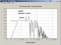
Just a very quick comparison between THAM15 loaded w/ 15TBX100 and 3015LF. If you want to go into that direction it might be worthwhile to take a look at Forsman's THAM-type layout: http://www.diyaudio.com/forums/subwoofers/224160-thorn-f1-learning-experiance-tapped-horn.html . A little longer path, add to that the cone correction......might just work very nicely.
Regards,
Attachments
Last edited:
Lots of info to absorb, but worth it.
I also built a few of Bills designs and currently have 2 3012LF loaded T39, and while I can't complain I too would like to dig a bit deeper. My autotuba while only going about 5 hz lower, sound great when they dig deep.
With such a small driver, would any of these designs adapt to a 12" or should I just stick with what I have untill I buy bigger/better drivers.
Hi Robin N Zone,
Just a very quick comparison between THAM15 loaded w/ 15TBX100 and 3015LF. If you want to go into that direction it might be worthwhile to take a look at Forsman's THAM-type layout: http://www.diyaudio.com/forums/subwoofers/224160-thorn-f1-learning-experiance-tapped-horn.html . A little longer path, add to that the cone correction......might just work very nicely.
Regards,
Oliver, thanks for the comparison! The 3015 doesnt look to bad in the THAM15.
If it isnt to difficult, would you be able to make a chart that compares the THAM15 and SS15, both with the 3015LF?
Still not sure what I would gain if I went with the THAM15 over the SS15.. A bigger box I believe?
Cone correction and such seems worth it yes, need to read up a bit more on that though..
Loudsubz, yeah I regoniced you from the BFM forum
I´m not sure, but there should be some designs that could use your drivers, perhaps better/deeper than your T39s.//Robin
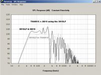
A SS15 has an actual internal volume of 224 litres disregarding the driver.
A Tham 15 has an internal volume of 144.5 litres measured in the same way.
The Tham works as well as it does by having a long path length for its size. It has a path length 75mm shorter than the SS15 when measured in a comparable way. But most of the posted sims for the Tham speakers exaggerate the internal volume by a large amount.
Martinsson defends this by his real world results.
When I compare the Tham 15 and the SS15 together using the 3015LF driver with comparable unfolding geometry and a sim volume within 6 percent of the measured volume, erring in favour of the Tham! I get the following directly comparable result. This is as fair a comparison as I can acheive.
Regards Xoc1
Attachments
When I compare the Tham 15 and the SS15 together using the 3015LF driver with comparable unfolding geometry and a sim volume within 6 percent of the measured volume, erring in favour of the Tham! I get the following directly comparable result. This is as fair a comparison as I can acheive.
Regards Xoc1
Xoc1 and Otb46, thanks for your graphs, very nice!
I mistakenly thought that the THAM15 was a bigger cab than the SS15, but I see now that is not the case
Xoc1, in your graph, is the black line the SS15 and the grey line the THAM15?
Which version of the SS15 was it? Your mod or the "standard" one?
I do like the folding style and size of the THAM15, but it seems like the SS15 might be a better choice for me, and the SS15 is still only half the size of my current T48s!
And as I´ve said before, I dont need to do exactly one sheet cabs, and could go a bit larger than the SS15 to gain more extension. But not sure that the drivers are up for all that much more extension anyway..
I´ve started making some Cad drawings for the SS15 extended, Jbells updated version in post #1499 Single Sheet Challenge thread, but I´m kinda stuck, only have the measurements for the panels, no angles and on the jpg I could find I simply cant read the measurements that gives the position on the panels.. Anyone knows if there is more info somewhere that I´ve missed? Should the angles be more or less the same as in the original SS15?
Jbell, if you are reading this, is there any possibility to get some more info/better quality pic of your sketches for the Extended?
I´d like to design my own horn from "scratch" or just make a slightly larger SS15 or THAM15, but I dont really know enough about horndesign to do that now...
I´ll post what I´ve got so far in cad in a little while, need to put on some measurements and stuff..
//Robin
Hi Robin
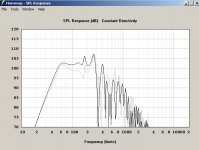
Regarding the sims, the SS15 sim is based on the original Jbell SS15 layout
The Tham sim is the same - but both sims are based on the actual geometry, not posted sim data, so that the 2 are comparable.
The modded SS15 layout has more of the lower frequency bump and a little bit less at 140.
Regards Xoc1
Thanks Martin!
Good to know about the sims Did you ever do a sim on your modifed version of the SS15? cant remember if I saw that or not..
What do you think about the SS15 Extended that Jbell posted a sketch of? Compared to your SS15 mod?
I saw your suggestion of a hornextender for the SS15 also, looks like a nice addition
Would there be any point in putting a 3015LF in your TH18 design? would it even work? Feels like cabs that big and heavy deserves a much more badass driver
Regards
Robin
Good to know about the sims
Did you ever do a sim on your modifed version of the SS15? cant remember if I saw that or not..What do you think about the SS15 Extended that Jbell posted a sketch of? Compared to your SS15 mod?
I saw your suggestion of a hornextender for the SS15 also, looks like a nice addition
Would there be any point in putting a 3015LF in your TH18 design? would it even work? Feels like cabs that big and heavy deserves a much more badass driver
Regards
Robin
I've not been checking in for awhile -- been installing. (it's baseball time....)
Yes there are tons of variation in the SS15 style folding (when you eliminate the singlesheet requirement)
However, as you go lower, you hit xmax before pmax.... The original ss15 is still my best compromise for the 3015lf between size/overall spl/extension.
Yes there are tons of variation in the SS15 style folding (when you eliminate the singlesheet requirement)
However, as you go lower, you hit xmax before pmax.... The original ss15 is still my best compromise for the 3015lf between size/overall spl/extension.
Jbell, Thanks for your reply!
Good to hear that you have so much installationwork
Are you still using the SS15 for installations?
I agree with you, I does look like the SS15 is the best compromise for the 3015LF, but that doesnt stop me from wanting to go slightly lower
I´d really like to try your Extended version that you posted a sketch for, been trying to make a drawing from you sketch and cutsheet, but I´m missing a few measurements.. Would you by any chance have a higher resolution pic or some other simple way for me to get those measurements?
The attached pdf is where I´m at right now. But I really dont know if the angles of the panels are correct, I´v used the size of the panels in Jbells cutsheet for the extended version, and used the angles from the original version, which probably isnt correct..
Like it is now, the conecorrection panels dont line up with the center of the cone, I dont like that, but maybe it doesnt matter? Or maybe its just wrong somewhere.
If the center of the conecorrection panel should line up with the center of the cone panel I gets wider then 4", and the first part of the horn gets a bit more narrow if panel I and G shall be the same size..
Also, Panel I and G are angled to be parallell with the sides of the cone, based on the drawing for the driver that Tb46 did. H is parallell to the baffle.
Any suggestions anyone?
//Robin
Attachments
Second attempt at drawing the Extended version
Hello everyone,
So, I found most of the measurements for Jbell´s sketch for the SS15 v2 Extended, post #1499 and #1526 SS thread, and made a new cad drawing based on those measurements.
I´m still a bit unsure about some things, but this is as close I can get it with the info I have on hand.
The position and angle of panel K is only based on measureing in Jbell´s sketch, I cant see any written measurements.. So not sure about that one at all, I´ll try to tweak it to get smoother expansion in that area.
Also, the cone correction is still a bit of center as you can see, I have no idea how much difference that makes, but it feels like it would be better if it was centered? I could of course center panel H over the driver, but then panel I and G wont be the same size and angles anymore. Now they almost parallell with the cone, panel I more so than G.
Jbell, if for some reason you do not wish to, or are able to share any more info on this design, please tell me so, and I wont ask anymore
If you on the other would like to give me some more input on this, it would be very much appreciated
The driver in the drawing is the drawing that Tb46 did earlier, updated with measurements from my drivers.
I´ll start to make a metric version, with more practical metric measurements, and accounting for the fact that the ply is 12mm and not 0.5" (12.7mm).
I´d like to reverseengineer Hornresp input from this drawing, but I´m not sure where to place S1, S2 and S3, and which kind of segment-type to select in Hornresp, any suggestions?
I´ll have a look at different drawings on the other versions of the SS15, and make a drawing as I think it should be, and post it here so you guys can correct me
//Robin
Attachments
So, here is a drawing that shows my guesses of where the different segments starts/ends.
S1 and S2 are the ones I´m most unsure about, I have no idea where they should be with the regards to the Cone volumecorrection.
S2 (1) ends at panel H. S2 (4) ends at an imaginary line between cone correction panels. That one feels logical for some reason..
S3, I´ve seen drawings with S3 where I´ve placed it, but also one with S3 further down the horn, but I have no idea about that reasoning..
S4 seems to be at the center of the driver at the baffle, perpendicular to the center of the hornpath, from the looks of other drawings, why its not further in, I dont know (say at my S4 (2) location? Maybe that has something to do with it being a Tapped Horn?
S5 is obvious, the hornmouth.
I´d really like to know the method to use when placeing the different segments, if there is something I can read up on this, or so, it be nice to know I wouldnt mind if someone simply told me where to place them, but prefer to know why, not just how
Thanks for your time guys!
//Robin
S1 and S2 are the ones I´m most unsure about, I have no idea where they should be with the regards to the Cone volumecorrection.
S2 (1) ends at panel H. S2 (4) ends at an imaginary line between cone correction panels. That one feels logical for some reason..
S3, I´ve seen drawings with S3 where I´ve placed it, but also one with S3 further down the horn, but I have no idea about that reasoning..
S4 seems to be at the center of the driver at the baffle, perpendicular to the center of the hornpath, from the looks of other drawings, why its not further in, I dont know (say at my S4 (2) location? Maybe that has something to do with it being a Tapped Horn?
S5 is obvious, the hornmouth.
I´d really like to know the method to use when placeing the different segments, if there is something I can read up on this, or so, it be nice to know
I wouldnt mind if someone simply told me where to place them, but prefer to know why, not just how Thanks for your time guys!
//Robin
Attachments
Hi Robin N Zone,
Looks like you're making progress. To maintain an even angle of expansion K should be orthogonal to C, and J and F should be parallel to each other.
For Hornresp you need to make a profile (roll-out) drawing of the enclosure to find the correct point for S3; you place S3 so that Hornresp matches the actual enclosure profile as closely as possible. S1/S2/S4/S5 are defined, and thus cannot be placed just anywhere one wants to. S1 ist the duct cross-section at the throat (against board F). S2 is the duct cross-section at a right angle to the duct path in the middle of the driver @ the horn throat side. S4 is the duct cross-section at a right angle to the duct path in the middle of the driver @ the horn mouth side. S5 is the horn mouth.
Once you have a Hornesp model you can experiment, and see if these are the optimum dimensions (I think they are, or they are very close.).
Regards,
Looks like you're making progress.
To maintain an even angle of expansion K should be orthogonal to C, and J and F should be parallel to each other.For Hornresp you need to make a profile (roll-out) drawing of the enclosure to find the correct point for S3; you place S3 so that Hornresp matches the actual enclosure profile as closely as possible. S1/S2/S4/S5 are defined, and thus cannot be placed just anywhere one wants to. S1 ist the duct cross-section at the throat (against board F). S2 is the duct cross-section at a right angle to the duct path in the middle of the driver @ the horn throat side. S4 is the duct cross-section at a right angle to the duct path in the middle of the driver @ the horn mouth side. S5 is the horn mouth.
Once you have a Hornesp model you can experiment, and see if these are the optimum dimensions (I think they are, or they are very close.).
Regards,
Last edited:
Oliver, thank you very much! Again well, some progress is made atleast
That was exactly the answers and definitions that I needed to move on
Tomorrow (later today, it's 3 in the morning here) I'll test out the new constraint functions in AutoCAD, looks like it will be perfect for making the roll out profile of the horn
I'm still curios whether Jbell ever built and tested this version of the cab, and if he preferred it over the original, and if anyone else built it. Couldn't find the answer to that in the single sheet thread.
I read up a bit on hornprofiles, and as I understand it, the segments of this kind of horn are parabolic, atleast if one consider a segment along two panels. Rectangular cross section, two sides parallel, the other two sides at an angle to create a linear expansion.
But I guess that a number of parabolic horn segments that expands more and more, create something like a exponential horn together?
I should be aiming for a linear expansion between S2 and S3?
Oliver, in your view, should S2 take the cone correction in account? Like S2 (1) in my drawing? That would give a very small S2. I was kinda thinking that the sim would use a larger S2, since the sim doesn't account for the volume of the cone, which is why we have the cone correction?
Well, know I have to sleep, have to be at work in 4 hours..
Regards
Robin
well, some progress is made atleastThat was exactly the answers and definitions that I needed to move on
Tomorrow (later today, it's 3 in the morning here) I'll test out the new constraint functions in AutoCAD, looks like it will be perfect for making the roll out profile of the horn
I'm still curios whether Jbell ever built and tested this version of the cab, and if he preferred it over the original, and if anyone else built it. Couldn't find the answer to that in the single sheet thread.
I read up a bit on hornprofiles, and as I understand it, the segments of this kind of horn are parabolic, atleast if one consider a segment along two panels. Rectangular cross section, two sides parallel, the other two sides at an angle to create a linear expansion.
But I guess that a number of parabolic horn segments that expands more and more, create something like a exponential horn together?
I should be aiming for a linear expansion between S2 and S3?
Oliver, in your view, should S2 take the cone correction in account? Like S2 (1) in my drawing? That would give a very small S2. I was kinda thinking that the sim would use a larger S2, since the sim doesn't account for the volume of the cone, which is why we have the cone correction?
Well, know I have to sleep, have to be at work in 4 hours..
Regards
Robin
Hi Robin,
As you noticed, the original SS15 uses an exponential expansion overall, with the individual segments being parabolic.
Your Hornresp S2 should be the sum of the cone center cross-section plus the duct cross-section (I think that's what your S2(1) is?). At S2(2) and S2(3) the duct is already expanding according to the flare rate. In other words: the use of the cone correction means, that the wood reflects what was simulated in the model to begin with (kind of). I think you should try to keep panel H centered on the driver.
Regards,
As you noticed, the original SS15 uses an exponential expansion overall, with the individual segments being parabolic.
Your Hornresp S2 should be the sum of the cone center cross-section plus the duct cross-section (I think that's what your S2(1) is?). At S2(2) and S2(3) the duct is already expanding according to the flare rate. In other words: the use of the cone correction means, that the wood reflects what was simulated in the model to begin with (kind of
). I think you should try to keep panel H centered on the driver.Regards,
- Status
- This old topic is closed. If you want to reopen this topic, contact a moderator using the "Report Post" button.
- Home
- Loudspeakers
- Subwoofers
- "Best" PA subdesign for the Eminence Kappalite 3015LF