Hi Robin N Zone,
To maintain an even angle of expansion K should be orthogonal to C, and J and F should be parallel to each other.
Oliver, I dont really get this part, well I understand what you mean and all, I just dont see why really. In the older versions of the SS15, K was perpendicular/orthogonal to C yes, but J and F have not been parallel to each other, atleast not in some of the drawings, for example the one I attached here.
I do agree that doing it the way you suggest should create an even angle of expansion up until S3, atleast it seems like that. But I´m not sure that it is a required?
After all, its not the actual angles but the areas/volumes they create that matters, no?
The angle of K in my drawing was based on the Jbell´s Extended sketch, but that sketch is a bit distorted in the angles, but it sure looks like he intended for K to be more or less parallel to J, doesnt it? Also the measurements given doesnt really lend themselves to do J and F parallel?
I´ll start to make the roll out later today, see where that takes us
")
Regarding S2, I think I´m getting what you are saying
From the middle of the driver up to panel H, taking the crossectional volume of the driver into account? I did S2 (1) from the baffle to panel H, not from the center of the dustcap. But, just so I understand, if we look at the older versions of the SS15, wasnt S2 calculated from baffle to the opposing panel? Not taking the volume of the driver in account? In effect S2 was much larger in reality then in the sim? Which is why the cone correction was implemented in the first place?
In my roll out, should I then measure from the driver and not just the baffle? That would get a bit complicated since the cone is, well a cone
Would be good to do that in 3D then perhaps.. I´m thinking that maybe a reasonable simplification could be to calculate S2 between the baffle and the imaginary line I did in my previous drawing that more or less bypasses the cone correction, keeping S2 rectangular? Then the cone correction panels fix the extra volume of the cone, making the real S2 rather close the the simulated simplified S2? Could that work?
It kinda seems to me that the cone correction part of the horn isnt really a hornsegment, more like a throat chamber or so?
//Robin
Attachments
Last edited:
Hi Robin N Zone,
You may well be correct with the angles you extracted from jbell's drawing.
The S2 in the roll-out should be a rectangular equivalent of the actual S2 including cone area; you add the area in the middle of the driver to the area of the duct @ that location, and divide by the common duct (internal enclosure) width. The same basically holds true for all the cross-sectional areas.
The original SS15 Hornresp simulation didn't take the cone volume into account. This (as well as, e.g.: not taking the room taken up by S4 on the other side of the driver into account) leads to differences between the model, and the build. These differences then appear as differences between the simulated and the measured response.
Looking forward to seeing your horn profile.
Regards,
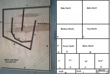
First attempt of Roll out
So, here goes, a couple of hours with Cad, and I´ve come up with this.
I´ve modified Jbell´s extended version somewhat, mainly to suit metric measurements, and to follow some of Olivers suggestions
I´ve accounted for the driver in both S2 and S5, and also in the corners around S2, by slicing 3D solids of the driver and horn, should be rather accurate, not perfect of course. I did not model the spokes of the basket for example.
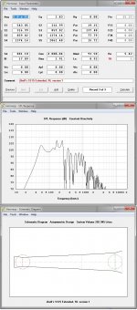
I put the values I got into Hornresp, and it doesnt look very good at all... So I hope I´ve done something wrong.. But now I´ve got to go home and sleep
See the attachments for more info
//Robin
So, here goes, a couple of hours with Cad, and I´ve come up with this.
I´ve modified Jbell´s extended version somewhat, mainly to suit metric measurements, and to follow some of Olivers suggestions
I´ve accounted for the driver in both S2 and S5, and also in the corners around S2, by slicing 3D solids of the driver and horn, should be rather accurate, not perfect of course. I did not model the spokes of the basket for example.
I put the values I got into Hornresp, and it doesnt look very good at all... So I hope I´ve done something wrong.. But now I´ve got to go home and sleep
See the attachments for more info
//Robin
Attachments
I forgot to add that the roll out has a volume of 217Liters, Hornresp says 202, so 15 L missing in the sim, perhaps that can be adjusted.
I´ll check the volume of the folded horn, but I expect som difference since I didnt use all that many lines to calculate the roll out.
Hopefully someone can find a serious error somewhere in all this, that would make the sim better if it was fixed, otherwise this design seems to need a fair bit of tweaking..
Also, Jbell stated that his Extended/v2 version should have 107"/ 2,7m, I only got around 98"/2,5m for some reason. Could in part be dependant on how one calculates the length in the corners, and I dont really know, just doing it the way I´ve seen others do it
//Robin
you didn't add the volume above the cone in your hornresp.
Too bad speaker manufacturers don't provide that information with the specifications.
Robin
You are very close to getting this right.
Good to see you taking this all on board and getting to grips with it.
By adjusting your sim using the horn wizard you can see that increasing S2 helps.
Your s2 and s4 is incorrect as you have not added the cross sectional area of the driver and baffle cut out to s2 and subtracted it from s4.
You have calculated the area, so divide that by the width of the cabinet, and add an imaginary line to your CAD drawing that distance below the baffle. Use that line to calculate your s2 and s4 areas.
Also your Sim Cms figure seems to be out I made Cms 1.36E-04
Pic added to save another 1000 words
Regards Xoc1
Attachments
Last edited:
Hi Robin N Zone,
One additional observation to what Martin (Xoc1) has pointed out: I think you could try S3 in the area where the first transition in the flare rate is (assuming board K being at right angle to board C). Also, K should be short enough, that there is an even expansion from S2 all the way to where I drew ?S3? (the gap between K and G). You are really close to the point where you have to export to AkAbak, and add a bunch of additional sections.
As Martin pointed out the 3015LF does not like to be "squeezed" too much, so if S2 gets to be too tight in the simulation (this seems to go hand in hand with the overall duct length growing longer), you may have to relax it a little which would have the added benefit of shortening the path just a little to get you back closer to the original SS15. This may seem counter-intuitive (as you want to get lower), but there is an optimum trade-off there somewhere. I would not worry too much about the height of the bottom peak, as this seems to be attenuated in real life, when looking at the work done by geitmans on Danley's SPUD there seems to be quite a flatening out of the response from the simulation to the measured response.
Regards,
Attachments
Last edited:
Hi Robin N Zone,
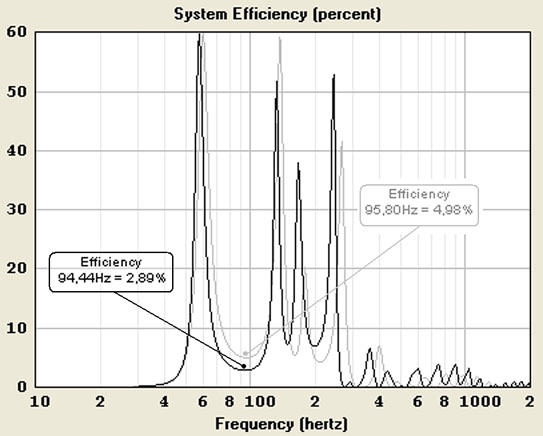
Just like tb46 said the peaks are usually not a major problem. It’s actually the 'dips' in efficiency that usually need attention.
You can check the efficiency values in the "System Efficiency" screens between the original SS15 and your 'new' model.
In the original SS15 you will see it is 4,98% and in your model it shows 2,89%.
For PA it is recommendable (especially for drivers with a relative high Qes) to keep it above 5% to prevent this area from running too early into power compression at high levels.
Last edited:
Thanks guys!
Thanks for all your answers and help guys!
I´ll have to sit down with the cad drawing tomorrow, see what I can do.
But, I dont really think I´ve missed the volume om above the cone? I drew a cross-section of S2, from panel H, and the area between the baffle and H is included in that cross-section. I then divided that with the internal width, 508mm, to get the distance used in the roll out.
I did not put that distance in the Cad though, I´ll do that tomorrow.
Same goes for S4, i calculated the area that the driver takes up, both cone and magnet assembly. Or rather, I calculated the area of the horn minus the drawin, as you can see in the pdf. but yeah, I did not used the resulting distance in the Cad.
Jbell, I tried to get this drawing as close to your sketch as possible, that is where the distance between baffle and H comes from. although, I did panel H somewhat smaller, and panel I and G ended up slightly longer. That is because I simple made an offset from an average line through the cone, 100mm up, and then adjusted the lenghts and angles slightly to be more whole mm´s and so.
Martin (Xoc1) in the grey line you made, I guess that you mean that I should use the calculated S2 and S4 lengths, and redraw those lines? It looks like the hornpath will get slightly longer in the last section then.
I´ll see if I can get something like that together tomorrow
Tb 46, thanks for your suggestion about S3, I agree that it seems logical I´ll have a look at that to And yes, K is perpendicular to B.
I´ll have a look at shortening it to get a more even expansion
Jbell,you still havent told us if you ever built your extended/v2 version that this is based on
Djim, thanks! Good to know that the peaks might not be problem
I did a gig yesterday, in a rather big veneu, for us atleast, the biggest we´ve used our T48s in sofar I think, something like atlest 200-300 squaremeters, and atlest 6m ceiling And the 2 T48´s were pounding hard, if anything we would have need more tops there But we used our small tops, a pair of LD systems LDEB 122, for the first time as tops And it was enough
The titans were in front of the center of a ~1.2m high permanent stage, on their sides, mouths together.
If we can get the same performance with the SS15´s as we do with our 80cm wide T48s, but in half the size, we would be very happy
Is that realistic? I know we´ll get less 100hz, but that should not be a problem.
Regards
Robin
Thanks for all your answers and help guys!
I´ll have to sit down with the cad drawing tomorrow, see what I can do.
But, I dont really think I´ve missed the volume om above the cone? I drew a cross-section of S2, from panel H, and the area between the baffle and H is included in that cross-section. I then divided that with the internal width, 508mm, to get the distance used in the roll out.
I did not put that distance in the Cad though, I´ll do that tomorrow.
Same goes for S4, i calculated the area that the driver takes up, both cone and magnet assembly. Or rather, I calculated the area of the horn minus the drawin, as you can see in the pdf. but yeah, I did not used the resulting distance in the Cad.
Jbell, I tried to get this drawing as close to your sketch as possible, that is where the distance between baffle and H comes from. although, I did panel H somewhat smaller, and panel I and G ended up slightly longer. That is because I simple made an offset from an average line through the cone, 100mm up, and then adjusted the lenghts and angles slightly to be more whole mm´s and so.
Martin (Xoc1) in the grey line you made, I guess that you mean that I should use the calculated S2 and S4 lengths, and redraw those lines? It looks like the hornpath will get slightly longer in the last section then.
I´ll see if I can get something like that together tomorrow
Tb 46, thanks for your suggestion about S3, I agree that it seems logical
I´ll have a look at that to And yes, K is perpendicular to B. I´ll have a look at shortening it to get a more even expansion
Jbell,you still havent told us if you ever built your extended/v2 version that this is based on
Djim, thanks! Good to know that the peaks might not be problem
I did a gig yesterday, in a rather big veneu, for us atleast, the biggest we´ve used our T48s in sofar I think, something like atlest 200-300 squaremeters, and atlest 6m ceiling
And the 2 T48´s were pounding hard, if anything we would have need more tops there But we used our small tops, a pair of LD systems LDEB 122, for the first time as tops And it was enough The titans were in front of the center of a ~1.2m high permanent stage, on their sides, mouths together.
If we can get the same performance with the SS15´s as we do with our 80cm wide T48s, but in half the size, we would be very happy
Is that realistic? I know we´ll get less 100hz, but that should not be a problem.
Regards
Robin
I have not worked out a cone correction for the 3015lf
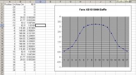
I have a correction curve for the Fane XB15 on a 18mm baffle as an example.
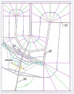
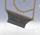
Firstly I model the cone volume and baffle cut out, and measure the cross section at different positions.
I then input the areas into a spreadsheet and calculate the equivalent height if the area was the full width of the speaker (in your case 503mm)
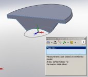
This gives me a cone correction curve that I can plot in the cad as an additional line that is used to calculate the folded volume, instead of the line of the baffle. The cone correction line is plotted on the top face of the baffle. The cone correction is simplified and averaged to 3 segments to be equivalent to the 3 timber sections.
This then gives a resultant horn section (as the 3rd screen grab.)
In your case I think you need to make S2 bigger, this seems to fill in the dip!
Use the Hornresp Loudspeaker Wizard to adjust S2 etc dynamically to see what works and adjust your fold accordingly. Then remeasure the unfolded horn and sim it again. Sometimes it takes a few iterations to get a reasonable result.
Regards Xoc1
I have a correction curve for the Fane XB15 on a 18mm baffle as an example.
Firstly I model the cone volume and baffle cut out, and measure the cross section at different positions.
I then input the areas into a spreadsheet and calculate the equivalent height if the area was the full width of the speaker (in your case 503mm)
This gives me a cone correction curve that I can plot in the cad as an additional line that is used to calculate the folded volume, instead of the line of the baffle. The cone correction line is plotted on the top face of the baffle. The cone correction is simplified and averaged to 3 segments to be equivalent to the 3 timber sections.
This then gives a resultant horn section (as the 3rd screen grab.)
In your case I think you need to make S2 bigger, this seems to fill in the dip!
Use the Hornresp Loudspeaker Wizard to adjust S2 etc dynamically to see what works and adjust your fold accordingly. Then remeasure the unfolded horn and sim it again. Sometimes it takes a few iterations to get a reasonable result.
Regards Xoc1
Attachments
Jbell,you still havent told us if you ever built your extended/v2 version that this is based on
Regards
Robin
yes, i've built MANY variations on the ss15. Most of them net minus in some respects to the original. Every time I get more 40hz, I get overall less total spl. In the end, total spl seems to rule the day.
The things that I have done that are net positives.
The 'wasted triangle' I eliminate to make S1 bigger, all else equal on original ss15. (very small but positive change) Big S2 actually makes cabinet lower without going longer. Problem is making that section 'rigid' enough. I typically take a piece of the round cutout and make a stiffening plate through that area. If your construction techniques aren't up to par, just build it the original way.
compression plate with 400-500cm opening. It really helps when 'wound up' to keep the cone 'linear'
2 -- dowell or 'broomstick' bracing about 6" apart. If you find one of those really long drill bits made to go through house walls (about 36" long) you can drill a couple holes from front to back and use dowells with 'rings' and glue where you go through each board.
2" vertical strip of wood attached to front panel in the center, (rt.angle to the front panel) it flexes ALOT there.
2" strip of wood attached to bottom panel from front to back -- bottom panel flexes alot.
metal grill on mouth to eliminate flex.
The original 2 angle boards from top/back and back/bottom. make a pair of them, 6" apart.
I've played with several different angle baffles in the upper back, no clear winner there, however smaller is better and it makes a great places for making 'routed out' handles and a recessed area for a speakon.
hope that helps... Really -- the original ss15 is just a pretty nice balanced cabinet for the 3015lf.
Good luck, and post pics/measurements when you make sawdust.
Last edited:
Hi Y'all,
Some more ponderings on the SS15:
I have not build or used a SS15, but I have tried on paper to improve on it. My result is, that the SS15 is a very good compromise, I feel a cone-corrected version should take that into account, and I furthermore think, that neither Hornresp nor AkAbak can provide a simulation that reflects what this driver/box combination is going to do at high power.
Particularly not the small S2 (high S2 compression) version of the cone-corrected SS15 (SS15CC?).
Someone has to build and measure, and compare models with different reduced S2s, e.g.: in jbells sketch he has about 1" between baffle and the other side of the duct, but this may well be with a compression plate, that would alter the geometry (it also would alter the Hornresp model, as you than have a throat chamber with an opening into the horn @ S2 (or two openings if you pull the cone compression all the way to the baffle, "opening" #1 points towards S3, and "opening" #2 points towards S1).
I'll attach a pdf with a look at Robin's first cone corrected drawing.
Regards,
Some more ponderings on the SS15
:I have not build or used a SS15, but I have tried on paper to improve on it. My result is, that the SS15 is a very good compromise, I feel a cone-corrected version should take that into account, and I furthermore think, that neither Hornresp nor AkAbak can provide a simulation that reflects what this driver/box combination is going to do at high power.
Particularly not the small S2 (high S2 compression) version of the cone-corrected SS15 (SS15CC?).
Someone has to build and measure, and compare models with different reduced S2s, e.g.: in jbells sketch he has about 1" between baffle and the other side of the duct, but this may well be with a compression plate, that would alter the geometry (it also would alter the Hornresp model, as you than have a throat chamber with an opening into the horn @ S2 (or two openings if you pull the cone compression all the way to the baffle, "opening" #1 points towards S3, and "opening" #2 points towards S1).
I'll attach a pdf with a look at Robin's first cone corrected drawing.
Regards,
Attachments
Thanks again guys
I really appreciate all the help and suggestions!
Martin, thanks for explaining your thinking on the conecorrection, looks very logical to me.
In my first attempt I just had a offset from an averaged coneshape, but I do see that your way makes more sense.
Btw, did you ever make a "final" conecorrected version of your TH18? And do you think it would be even a half good idea to build it in 12mm birch (more bracing) and the 3015lf? It looked like the driver simmed rather good in your cab if nothing else.
Jbell, thanks for your answers and tips
I must say that I´m kinda leaning against a more original SS15, but maybe with the conecorretion, but maybe not as extreme as the one I drew first.
While I´d really like to spend more time on optimising the design, I more or less have a deadline, I need two more subs on saturday.. and I´d prefer to not need to rent subs, I probably gonna need to rent 2 Pioneer CDJ-2000´s to manage the two gigs so
I´d like to start building tomorrow, but that doesnt mean that I cant build a different version of the SS15 in the near future, but would of course prefer to build a version that I´d stay with for a while.
I was thinking to put routered handles in the upper back corner, with either a corner "reflector" the whole way, or perhaps just covers around handles? Seems to me that it wont be much of a loss to loose some volume in the corner?
Oliver, thanks for spending all the time you do with drawings and all SS15CC seems like a good name for the cone corrected version, lets go with that?
I will probably only build one version of the SS15CC now, but who knows Dont know about any other builds here in Sweden to compare to sadly..
Now, back to cad and hornresp to see if I can get it a bit better, the sim looks a lot better with Olivers suggested 512cm^2 S2, big difference, so I´ll make a cad drawing with that and his suggestion on S3 location.
I´ll post when I have something to post
//Robin
I really appreciate all the help and suggestions!
Martin, thanks for explaining your thinking on the conecorrection, looks very logical to me.
In my first attempt I just had a offset from an averaged coneshape, but I do see that your way makes more sense.
Btw, did you ever make a "final" conecorrected version of your TH18? And do you think it would be even a half good idea to build it in 12mm birch (more bracing) and the 3015lf? It looked like the driver simmed rather good in your cab if nothing else.
Jbell, thanks for your answers and tips
I must say that I´m kinda leaning against a more original SS15, but maybe with the conecorretion, but maybe not as extreme as the one I drew first.
While I´d really like to spend more time on optimising the design, I more or less have a deadline, I need two more subs on saturday.. and I´d prefer to not need to rent subs, I probably gonna need to rent 2 Pioneer CDJ-2000´s to manage the two gigs so
I´d like to start building tomorrow, but that doesnt mean that I cant build a different version of the SS15 in the near future, but would of course prefer to build a version that I´d stay with for a while.
I was thinking to put routered handles in the upper back corner, with either a corner "reflector" the whole way, or perhaps just covers around handles? Seems to me that it wont be much of a loss to loose some volume in the corner?
Oliver, thanks for spending all the time you do with drawings and all
SS15CC seems like a good name for the cone corrected version, lets go with that?I will probably only build one version of the SS15CC now, but who knows
Dont know about any other builds here in Sweden to compare to sadly.. Now, back to cad and hornresp to see if I can get it a bit better, the sim looks a lot better with Olivers suggested 512cm^2 S2, big difference, so I´ll make a cad drawing with that and his suggestion on S3 location.
I´ll post when I have something to post
//Robin
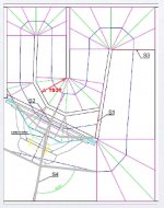
So, the next cad drawing is "ready".
I´ve calculated the conecorrection the way that Xoc1 showed earlier today, and used that together with the suggestion of 512cm^2 S2, and moved S3 to the second 180bend.
I calculated the area that the driver takes up at the S4 location, and put the equivalent in the Cad. This whole operation lost me about 10cm of hornpath.
It does sim better for sure, so thanks guys I´m still not sure if panel I, H and G have a good shape or not, probably possible to adjust those some more.
I just took the cone correction curve and moved it to get 101mm S2. I dont really know how Martin gets his shapes, I cant really see the connection between his panelshape and the cone correctionshape, but I´m sure there is some nice correlation
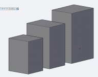
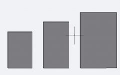
I also made a simple comparison of relative sizes between, from left to right, the SS15CC, the TH18 (in 12mm ply) and my Titan48s. They are all lined up with the horn openings to the floor and front.
The SS15CC sure is a lot smaller than the T48s But the TH18 are quite a lot smaller also, and it looks like I could fit 4 of those in my van, where I can only get in 2 T48s, and that would be nice
So, now I´m basically thinking: Should I spend many more hours trying to get a good design from what I´ve started with the SS15CC, which may or may not turn out better than the original version with say a smaller baffle opening.
Or, just go for the standard SS15 with the simple mods that Jbell suggested earliger?
Or, since I dont really need to stick to one sheet, just go with the Xoc1 TH18, but in 12mm ply, afterall, it will only get an 3015ÖLF, not a multiKW 18", so should be fine with some extra braces, I think?
I do like the response that the 3015LF seems to get in the TH18, and if I´m willing to go bigger than the SS15, there is no point in trying to design something myself when Martin has already made such a nice design
The downside of the TH18 with a 3015LF would be that it is a rather big cab, and as such really deserves a better driver I think, but it would get me more out of the drivers I have on hand now..
And it would be nice with subs the size of the SS15 for sure.
This is the kind of decisions I´m really bad at
I´ve attached the cad drawing and a Hornresp export for the SS15CC v2.
Regards
Robin
I´ve calculated the conecorrection the way that Xoc1 showed earlier today, and used that together with the suggestion of 512cm^2 S2, and moved S3 to the second 180bend.
I calculated the area that the driver takes up at the S4 location, and put the equivalent in the Cad. This whole operation lost me about 10cm of hornpath.
It does sim better for sure, so thanks guys
I´m still not sure if panel I, H and G have a good shape or not, probably possible to adjust those some more. I just took the cone correction curve and moved it to get 101mm S2. I dont really know how Martin gets his shapes, I cant really see the connection between his panelshape and the cone correctionshape, but I´m sure there is some nice correlation
I also made a simple comparison of relative sizes between, from left to right, the SS15CC, the TH18 (in 12mm ply) and my Titan48s. They are all lined up with the horn openings to the floor and front.
The SS15CC sure is a lot smaller than the T48s
But the TH18 are quite a lot smaller also, and it looks like I could fit 4 of those in my van, where I can only get in 2 T48s, and that would be nice So, now I´m basically thinking: Should I spend many more hours trying to get a good design from what I´ve started with the SS15CC, which may or may not turn out better than the original version with say a smaller baffle opening.
Or, just go for the standard SS15 with the simple mods that Jbell suggested earliger?
Or, since I dont really need to stick to one sheet, just go with the Xoc1 TH18, but in 12mm ply, afterall, it will only get an 3015ÖLF, not a multiKW 18", so should be fine with some extra braces, I think?
I do like the response that the 3015LF seems to get in the TH18, and if I´m willing to go bigger than the SS15, there is no point in trying to design something myself when Martin has already made such a nice design
The downside of the TH18 with a 3015LF would be that it is a rather big cab, and as such really deserves a better driver I think, but it would get me more out of the drivers I have on hand now..
And it would be nice with subs the size of the SS15 for sure.
This is the kind of decisions I´m really bad at
I´ve attached the cad drawing and a Hornresp export for the SS15CC v2.
Regards
Robin
Attachments
Apperently it didnt work to post a rarfile, so here comes a link to a folder on my google drive, there is an R14 version of the cad file, and 2007 version, and also the Hornresp export, and the size comparision drawing I made in 2007.dwg format.
https://drive.google.com/folderview?id=0B8yhy6Gs5tGqTTdSMkxLbEVFY1U&usp=sharing
Regards
Robin
https://drive.google.com/folderview?id=0B8yhy6Gs5tGqTTdSMkxLbEVFY1U&usp=sharing
Regards
Robin
So, version3 now
Oliver (TB46) gave me a suggestion earlier today, which gave more S1, and much nicer shape to the whole S3-S4 region, it did also sim better.
Attached is the drawing as a pdf, and a hornresp export.
The dwg in R14 format can be found at the same link to my google drive in the previuos post.
I ran a few sims of the original SS15, and also of a mod that Xoc1 posted a while back in the single sheet challenge thread.
None of those take the volume of the cone into account as far as I can see, neither in S2 or S4, so S2 gets bigger and S4 smaller in reality, which atleast in the sims gives more 40hz, less 60-100hz.
So it seems to me that taking the volume of the driver into account early on should jield a cad that performs closer to the sim, no?
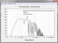
If there is also a performance benefit, I´m not to sure. See the attached pic that compares mine and Tb46´s SS15CC v3 with the SS15 Xoc1 mod, when the later has the volume of the driver roughly added to S2, subtracted from S4.
The other point of the cone correction seems to be better cone control at high drivelevels, but we dont se that in the sims... Could a smaller cut out in the baffle(as Jbell suggested yesterday) on say the Xoc1 mod do much the same thing?
Not sure how to move forward now..
I think I need to make sawdust soon
Regards
Robin
Oliver (TB46) gave me a suggestion earlier today, which gave more S1, and much nicer shape to the whole S3-S4 region, it did also sim better.
Attached is the drawing as a pdf, and a hornresp export.
The dwg in R14 format can be found at the same link to my google drive in the previuos post.
I ran a few sims of the original SS15, and also of a mod that Xoc1 posted a while back in the single sheet challenge thread.
None of those take the volume of the cone into account as far as I can see, neither in S2 or S4, so S2 gets bigger and S4 smaller in reality, which atleast in the sims gives more 40hz, less 60-100hz.
So it seems to me that taking the volume of the driver into account early on should jield a cad that performs closer to the sim, no?
If there is also a performance benefit, I´m not to sure. See the attached pic that compares mine and Tb46´s SS15CC v3 with the SS15 Xoc1 mod, when the later has the volume of the driver roughly added to S2, subtracted from S4.
The other point of the cone correction seems to be better cone control at high drivelevels, but we dont se that in the sims... Could a smaller cut out in the baffle(as Jbell suggested yesterday) on say the Xoc1 mod do much the same thing?
Not sure how to move forward now..
I think I need to make sawdust soon
Regards
Robin
Attachments
The SS15 version I drew predates my use of any TH cone correction.
The TB46 mod version looks good.
The cone correction should ensure the bottom end response is fairly close to the sim.
Actual performance of the cab will be very dependent on your build and how well you brace the cabinet.
Regards Martin (Xoc1)
The TB46 mod version looks good.
The cone correction should ensure the bottom end response is fairly close to the sim.
Actual performance of the cab will be very dependent on your build and how well you brace the cabinet.
Regards Martin (Xoc1)
Martin, thanks for your answers!
Yes, I guessed that was the case for your version of the SS15. But still, when I roughly added/subtracted the volumes of the driver, your version simmed better then "mine" I think, so it really seems like a large S2 is the way to go for the Kappalite, maybe even more so with the newer ones.
So my question would be, what other benefits will the cone correction give, apart from making the sim closer to reality?
I´m not convinced that the V-loading that I´ve been looking at would give all that much more even loading of the cone, it feels almost more uneven than just a flat panel. I mean, the volume towards S1 dont really move anywhere?
The main advantage that I can see with that style of conecorrection and folding is that it gives a longer path, but that doesnt seem to do any good, atleast not when the box size is the same and the driver is the 3015LF.
Using a smaller round opening in the baffle, like the 4-500cm^2 that Jbell suggest, should create a more even load on the driver I would think, and increase the compression a bit.
One of the gigs we had booked on saturday just got moved 3 weeks, so now I´m not in a desperate need for 2more subs, so there is some more time to design something good now
Regards
Robin
Long time no post!
Hello again guys!
Been a bit busy the last few weeks, sadly only partially with subwoofer design...
But I´ve done a bit atleast, and I´ve decided on what direction and such, finalising a version of the SS15, mainly based on the one that Xoc1 did a while back, but slightly wider and some other small changes, to optimise the sheet even further
I´ve decided to do a bit more bracing than the "standard" SS15, and to cheat a bit, I´ll make the braces out of 9mm BB, and use a full sheet of 12mm BB for the rest, so it wont really be an SS15, but thats fine be me
I´ve made a few versions of the drawings and sims with a the conecorrection, and I just cant get it to sim better than Xoc1´s version, even when I take the cone into consideration on the Xoc1 design.
A large S2 seems to be critical for the newer Kappalites, so I´m going with the Xoc1 (close to Jbells original) basedesign, and tweak it a bit
One thing that Jbell have suggested is to reduce the opening in the baffle to something like 3-400cm^2, much the same way the baffle in my Titans are made. I´m thinking that a round opening would load the cone more evenly than a square opening or the "double S shape" opening that was suggested for Xoc1´s TH18 a while back.
Any other suggestions about that? What shape would be best? I guess that max performance and max durability of the driver might not go hand in hand here, and I´d opt for durability here.
I would then need to mount the driver on a spacer, 12mm should be best, then I´ll get about 18mm clearance for the cone and surround, xlim is 17mm, so if the cone hits the baffle it will not really matter much
Perhaps 9mm spacer could be used, but then I´ll only get about 15mm clearance, with an xmax of 11mm it should work fine, but a bit to small margin I guess? I dont think my current amps can drive the 3015LF to 15mm excursion, even less likely considering powercompression and limiters set to maybe max 60-65V, but still...
I´m also thinking about putting a smallish cornerbrace/"reflector" in the lower corner, without constricting the hornpath at all, so really only taking away nonlinear extra volume in the hornpath. This is mainly to get a cut away lower corner, and then save a bit of wood on the bottom and back panels. otherwise Xoc1´s interior hornpanels dont actually fit on the one sheet
Also, I can then put some nice 80mm wheels in the lower corner, I know I know, small cabs, not really necessary to have wheels, but I´m building these to get smaller easier to handle alone cabs so they´ll have wheels
Anyone seeing a big problem with a "reflector" like that?
I´m also thinking of routing a handle in the top of the cab, a cutout in the top hornpanel, and 2 cutouts in the top, on each side, coverd with 45degree "reflectors" each side. More or less like a barhandle, only routed into the cab instead I know, loosing a bit of cabvolume there to, but must have handles, these will be rental cabs. My plan is that these will be light enough to lift in one hand, and it should work good to use that handle to roll them on the wheels, so wount need to lift the much anyway
This handle will also just take away nonlinear cornervolume in the cab, so hopefully not contstricting the path.
I´d like to have routered handles in the sides also, but that might take away to much S1/S2 area, cause thats where they´d end up..
What do you guys think? Am I way of base here? I need to start building this week, for real this time
I can upload a pdf with the latest version of the drawing I have tomorrow
Thanks for all help guys!
//Robin
Hello again guys!
Been a bit busy the last few weeks, sadly only partially with subwoofer design...
But I´ve done a bit atleast, and I´ve decided on what direction and such, finalising a version of the SS15, mainly based on the one that Xoc1 did a while back, but slightly wider and some other small changes, to optimise the sheet even further
I´ve decided to do a bit more bracing than the "standard" SS15, and to cheat a bit, I´ll make the braces out of 9mm BB, and use a full sheet of 12mm BB for the rest, so it wont really be an SS15, but thats fine be me
I´ve made a few versions of the drawings and sims with a the conecorrection, and I just cant get it to sim better than Xoc1´s version, even when I take the cone into consideration on the Xoc1 design.
A large S2 seems to be critical for the newer Kappalites, so I´m going with the Xoc1 (close to Jbells original) basedesign, and tweak it a bit
One thing that Jbell have suggested is to reduce the opening in the baffle to something like 3-400cm^2, much the same way the baffle in my Titans are made. I´m thinking that a round opening would load the cone more evenly than a square opening or the "double S shape" opening that was suggested for Xoc1´s TH18 a while back.
Any other suggestions about that? What shape would be best? I guess that max performance and max durability of the driver might not go hand in hand here, and I´d opt for durability here.
I would then need to mount the driver on a spacer, 12mm should be best, then I´ll get about 18mm clearance for the cone and surround, xlim is 17mm, so if the cone hits the baffle it will not really matter much
Perhaps 9mm spacer could be used, but then I´ll only get about 15mm clearance, with an xmax of 11mm it should work fine, but a bit to small margin I guess? I dont think my current amps can drive the 3015LF to 15mm excursion, even less likely considering powercompression and limiters set to maybe max 60-65V, but still...
I´m also thinking about putting a smallish cornerbrace/"reflector" in the lower corner, without constricting the hornpath at all, so really only taking away nonlinear extra volume in the hornpath. This is mainly to get a cut away lower corner, and then save a bit of wood on the bottom and back panels. otherwise Xoc1´s interior hornpanels dont actually fit on the one sheet
Also, I can then put some nice 80mm wheels in the lower corner, I know I know, small cabs, not really necessary to have wheels, but I´m building these to get smaller easier to handle alone cabs so they´ll have wheels
Anyone seeing a big problem with a "reflector" like that?
I´m also thinking of routing a handle in the top of the cab, a cutout in the top hornpanel, and 2 cutouts in the top, on each side, coverd with 45degree "reflectors" each side. More or less like a barhandle, only routed into the cab instead
I know, loosing a bit of cabvolume there to, but must have handles, these will be rental cabs. My plan is that these will be light enough to lift in one hand, and it should work good to use that handle to roll them on the wheels, so wount need to lift the much anyway This handle will also just take away nonlinear cornervolume in the cab, so hopefully not contstricting the path.
I´d like to have routered handles in the sides also, but that might take away to much S1/S2 area, cause thats where they´d end up..
What do you guys think? Am I way of base here? I need to start building this week, for real this time
I can upload a pdf with the latest version of the drawing I have tomorrow
Thanks for all help guys!
//Robin
- Status
- This old topic is closed. If you want to reopen this topic, contact a moderator using the "Report Post" button.
- Home
- Loudspeakers
- Subwoofers
- "Best" PA subdesign for the Eminence Kappalite 3015LF