Is your gateresistors close to the gates ? I think this can be important.
Thanks Tord, I tried that, no difference.
yeah, or trying 220R instead....
Thank you too, Gerd. I tried that also, and no difference either.
O.K. Go on in the list....)
Hi Gerd,
Please check your email, including SPAM...
Thanks.
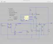
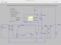
I made a Spice with the BAF 2015 circuit but I have no IXFN model
I took for a start the Semisouth R100, lower voltage and about 1.4A current and
it works..... INCREDIBLE it behaves like a lamb.... why not in reality?
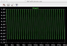
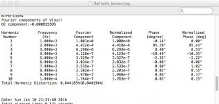
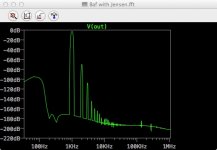
you see the circuit in Spice, the gain 20dB, the distortion 0.04 and the THD graph with dominant k2.
The LTSpice file is also in the attachement. Kill the ending .txt
Does anyone have models nearer to the real Mosfet?
I took for a start the Semisouth R100, lower voltage and about 1.4A current and
it works..... INCREDIBLE it behaves like a lamb.... why not in reality?
you see the circuit in Spice, the gain 20dB, the distortion 0.04 and the THD graph with dominant k2.
The LTSpice file is also in the attachement. Kill the ending .txt
Does anyone have models nearer to the real Mosfet?
Attachments
Last edited:
Lab power supplies are evil.
Or overlooking error in his wiring.
2pD
All parts values were confirmed before installation. I triple checked the wiring logic and for tight connections. There is no issue after 3 days of pretty intense scrutiny.
The lab supplies MAY be evil, but not likely as I used them regularly. Moreover, I cannot explain the runaway current draw beyond 4.5A on a single output device and voltage drop from +60 to +32 while the output device surges to 170°F.
If there is a way I can be sure that my well-respected, normally bullet-proof Rohde & Schwarz lab supplies are truly the culprit, then I will consider biting the bullet and building that Variac-based, cap bank PSU I had already planned.
I wish someone else is also building this and can share their actual experience so I can find out where I am going wrong.
Just use the 9V battery and trimpot on 4.7V source and you'll will know straight away if it is your power supply.
I will need to read over everything you have done to make a proper comment.
The one thing I can say is the IXYS hockey puck has very high transconductance which is extremely sensitive to small changes in Vgs so I'm not too surprised by your observations.
I will need to read over everything you have done to make a proper comment.
The one thing I can say is the IXYS hockey puck has very high transconductance which is extremely sensitive to small changes in Vgs so I'm not too surprised by your observations.
Just one more possibility.
Based on the fact these devices are so sensitive to Vgs, your issue could be due to the fact you are using 4N37 instead of Nelson's recommended 4N35.
I haven't compared the 2 devices on the data sheet but this is a real possibility.
Either way try increasing the resistor to 50k to lower current a bit.
You may as well start with doing what ZM suggested first though.
Gentlemen,
Here's the latest:
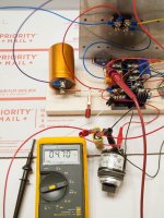
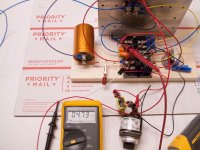
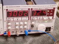
2pD, I biased with a 9V and pot for 4V7 as you aksed and shown in photo 1. Result is the same current runaway as in photo 2.
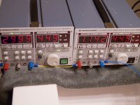
ZM, I hooked up one supply only at +30V and the device drew 0.7A shown in photo 3 with no current runaway - but then it's not doing much. Bias also with 9V battery at 4V7.
Generg, you can see under the red probe 2 orange caps - these are paralleled and measured at 260µF, also 9V1 zener is gone.
Here's the latest:
2pD, I biased with a 9V and pot for 4V7 as you aksed and shown in photo 1. Result is the same current runaway as in photo 2.
ZM, I hooked up one supply only at +30V and the device drew 0.7A shown in photo 3 with no current runaway - but then it's not doing much. Bias also with 9V battery at 4V7.
Generg, you can see under the red probe 2 orange caps - these are paralleled and measured at 260µF, also 9V1 zener is gone.
Attachments
Last edited:
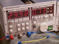
lower half at 30V - can you bias it with pot to 3A2 , to stay steady ? ?
Yep - one supply to lower half, battery biased at 4V73, output at 30V, 3A22. See photos. This means the bias regulator is somehow not coping well with these devices, right?
EDIT: spoke a little too soon - at 4V71, the current kept drifting up until it pushed past 3V2 and the voltage drops due to CC operation in the supply. Perhaps the device is the problem?
Attachments
Last edited:
it is 4N37 on schm
Papa is well aware of fact that bjt side of 4N37 is having more voltage oomph than same of 4N35
My memory is like a bloody sieve. For some reason my 2.5 brain cells kept saying 4N35
Still motorboating.
How about you short the 22 ohm feedback resistor to ground?
The feedback 22R is one side to ground and the other to the junction of the 220R and yellow lead from the Jensen now. Is this what you mean or should I change it to something different?
- Status
- This old topic is closed. If you want to reopen this topic, contact a moderator using the "Report Post" button.
- Home
- Amplifiers
- Pass Labs
- BAF 2015 Coverage