You need a preamp with low output impedance, preferably below 100 Ohms, so a passive pot without buffering is unlikely to work.
Well, it's more than a pot but it's not active. It sounds absolutely glorious, especially at the price. I've had plenty other preamps - from a 1979 Threshold SL-10 with my first paycheck to all manners of high-buck tube stuff, and this beats them ALL.
I sincerely hope it will work. The source feeding it does have a low 20 Ohm output impedance.
So I worked at it a little more: replaced the opto, crimped wires properly to rings or spades where possible, and traced the signal according to the schematic. I built only one channel. And it powered up, but it is far from playing music at this point. In fact, it is only working electrically, but it is not an amplifier. Here are my observations:
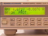
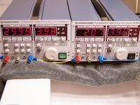
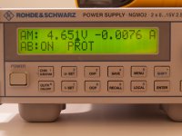
Setup: The bias supply was set at +4.67V and I was able to vary in 1mV steps to see the effects. The rail supply was set at +60V current limited to 4A.
1. I tried to set DC offset with the input shorted. No go. Motor-boating. In addition to shorting the input. I also tried connect the input to my PC headphone jack. No go either.
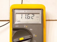
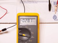
2. With the input not shorted, the output would start at +35VDC, then over a minute or so, drops to around ±50mV, but it does not stay there. I lowered the bias in 1mV steps and kept chasing after it.
3. Then the rail supply starts to draw more current and less voltage. With the output MOSFET at about 160ºF, rail voltage drops to +32V but kept crashing into the current limit that I had set to 4A. The drive MOSFET is quite a bit cooler at 95ºF or so. The heatsink is 12 x 8 x 3.5 with 40 fins, no fan.
So my questions are:
1. Why is it trying to draw more current than 4A?
2. Why is it drawing only +32V when +60V is available?
3. What buffer should I use?
Very curious now!
Setup: The bias supply was set at +4.67V and I was able to vary in 1mV steps to see the effects. The rail supply was set at +60V current limited to 4A.
1. I tried to set DC offset with the input shorted. No go. Motor-boating. In addition to shorting the input. I also tried connect the input to my PC headphone jack. No go either.
2. With the input not shorted, the output would start at +35VDC, then over a minute or so, drops to around ±50mV, but it does not stay there. I lowered the bias in 1mV steps and kept chasing after it.
3. Then the rail supply starts to draw more current and less voltage. With the output MOSFET at about 160ºF, rail voltage drops to +32V but kept crashing into the current limit that I had set to 4A. The drive MOSFET is quite a bit cooler at 95ºF or so. The heatsink is 12 x 8 x 3.5 with 40 fins, no fan.
So my questions are:
1. Why is it trying to draw more current than 4A?
2. Why is it drawing only +32V when +60V is available?
3. What buffer should I use?
Very curious now!
Attachments
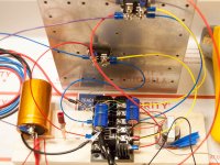
So I worked at it a little more: replaced the opto, crimped wires properly to rings or spades where possible, and traced the signal according to the schematic. I built only one channel. And it powered up, but it is far from playing music at this point. In fact, it is only working electrically, but it is not an amplifier. Here are my observations:
Setup: The bias supply was set at +4.67V and I was able to vary in 1mV steps to see the effects. The rail supply was set at +60V current limited to 4A.
1. I tried to set DC offset with the input shorted. No go. Motor-boating. In addition to shorting the input. I also tried connect the input to my PC headphone jack. No go either.
2. With the input not shorted, the output would start at +35VDC, then over a minute or so, drops to around ±50mV, but it does not stay there. I lowered the bias in 1mV steps and kept chasing after it.
3. Then the rail supply starts to draw more current and less voltage. With the output MOSFET at about 160ºF, rail voltage drops to +32V but kept crashing into the current limit that I had set to 4A. The drive MOSFET is quite a bit cooler at 95ºF or so. The heatsink is 12 x 8 x 3.5 with 40 fins, no fan.
So my questions are:
1. Why is it trying to draw more current than 4A?
2. Why is it drawing only +32V when +60V is available?
3. What buffer should I use?
Very curious now!
You either have miswiring, bad component or oscillations.
For testing purposes instead of buffer you can use headphone amplifier or any preamplifier with low output impedance.
I wonder if the ccs circuit may have to be fine tuned ? The voltage drop across the diode in the 4n37 may not be exactly 1v at 3ma. If you look at the PDF it's specified as 1.3 to 1.5 v @ 10ma. I wonder if it might be a good idea to measure the actual voltage drop in the circuite ?
http://www.vishay.com/docs/81181/4n35.pdf
http://www.vishay.com/docs/81181/4n35.pdf
I wonder if the ccs circuit may have to be fine tuned ? The voltage drop across the diode in the 4n37 may not be exactly 1v at 3ma. If you look at the PDF it's specified as 1.3 to 1.5 v @ 10ma. I wonder if it might be a good idea to measure the actual voltage drop in the circuite ?
http://www.vishay.com/docs/81181/4n35.pdf
Thank you for your comments.
Given the extremely low parts count in this circuit, the interdependencies are likely subtle and intricate, and I would hesitate to guess before hearing from Papa himself. He published the this schematic for a reason and far from it for me to be second guessing his choice of topology or components. My thinking is that there may be a gremlin or two that had not yet been called out in his BAF2015 video presentation or this thread. I hope he can enlighten us at some point.
Thanks again.
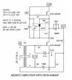
upper half of amp is self biasing mechanimus ; maybe just (red squared) 10K resistor can be lowered , if you stumble on thirsty gate mosfet , but nothing else
all you need is to chase proper bias voltage for lower brick ( noted as 4V7) , to bring marked node (lower drain) to 28V potential ..... which means equilibrium of resulting static impedances of lower and upper half
all you need is to chase proper bias voltage for lower brick ( noted as 4V7) , to bring marked node (lower drain) to 28V potential ..... which means equilibrium of resulting static impedances of lower and upper half
Attachments
upper half of amp is self biasing mechanimus ; maybe just (red squared) 10K resistor can be lowered , if you stumble on thirsty gate mosfet , but nothing else
all you need is to chase proper bias voltage for lower brick ( noted as 4V7) , to bring marked node (lower drain) to 28V potential ..... which means equilibrium of resulting static impedances of lower and upper half
Hi ZM,
Thanks for your comments. Would you advise using a 10K pot in its place so it's easier to home in on the right value? Also, how would you solve the input impedance issue? I do not have a low-impedance preamp - can I strap a 10R across the input to adjust DC offset?
10K , not an issue ; if you are thinking about it , just use 8K2 or 6K8
regarding preamp/preceding stage impedance - no free lunch ; you need to use stage with 50R or less output impedance
if you are having enough greenies to pay for that sort of hardware , it's better not to pinch regarding preamp
regarding setting procedure - no load , input grounded**
**just common practice , to prevent possible spray of junk in input ; NB that input griounding is having exactly nothing with lower mosfet gate potential and output node voltage potential
10K , not an issue ; if you are thinking about it , just use 8K2 or 6K8
regarding preamp/preceding stage impedance - no free lunch ; you need to use stage with 50R or less output impedance
if you are having enough greenies to pay for that sort of hardware , it's better not to pinch regarding preamp
regarding setting procedure - no load , input grounded**
**just common practice , to prevent possible spray of junk in input ; NB that input griounding is having exactly nothing with lower mosfet gate potential and output node voltage potential
Hi ZM,
I don't have the other values on hand so I will find a 10K pot and adjust it watching for the 28V and hope it will stabilize. On the DC offset side, I started out with the input shorted. That went nowhere as I previously noted. It wasn't until I left them disconnected as per my last picture that the DC offset was in the mV range.
As for the preamp, I do use this LDR3x Passive Preamp Controller with Remote | Tortuga Audio with my input source which is spec'd as a 20R output. Do you think it would work? If it won't then I have to break another piggybank for a preamp - not a battle I want with my CFO/Wife at this point, hence the question about integrating a simple buffer stage in front of the Jensen.
no, 10K resistor isn't critical , but I would lower it just for better sleep , nothing else ; ther is no sweet spot or anything which you can find with pot instead
IF everything is connected as per schematic , and IF PSU is correct and IF you have some variable and adequate voltage (say between 3V5 and 6V5, without looking at exact mosfet data) to feed 4V7 node , then I can't see how circuit can't be set as Papa prescribed .
tripple check everything
also - primary of xformer (and anything connected directly to it) is of importance only in AC realm of amp's operation ; you can tie baloon to it or hang Golden Gate Bridge on it , as long they're silent , they're invisible to setting procedure

your LDR preamp - I can't see on linked page - what's last functional block/element , connected to following stage (amp) ?
I would also try for a test much higher gatestoppers and....
The PsU you use .....is it possibly making trouble?
Hi Gerd,
Would you please suggest some values for gatestoppers? The PSU's are already internally diode-strapped for serial connection and set for CC operation, they are normally very quiet and stable so I wonder what kind of trouble you think they can cause?
ZM,
Look at what I found for a 10K pot - courtesy of my BLMC project ;-)
Attachments
no, 10K resistor isn't critical , but I would lower it just for better sleep , nothing else ; ther is no sweet spot or anything which you can find with pot instead
IF everything is connected as per schematic , and IF PSU is correct and IF you have some variable and adequate voltage (say between 3V5 and 6V5, without looking at exact mosfet data) to feed 4V7 node , then I can't see how circuit can't be set as Papa prescribed .
tripple check everything
also - primary of xformer (and anything connected directly to it) is of importance only in AC realm of amp's operation ; you can tie baloon to it or hang Golden Gate Bridge on it , as long they're silent , they're invisible to setting procedure
your LDR preamp - I can't see on linked page - what's last functional block/element , connected to following stage (amp) ?
ZM,
Thanks again!
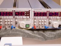
Gerd asked a question about my PSU as well, as I already replied. The supplies are shown as in the pictures: for bias, it is from one PSU 4V7 variable in 1mV steps, limited to 1A; and for the rail, it is from 2 serially connected PSU's serial connected to get +60 and limited to 4A. The connected PSU's can deliver +60V at up to 10A with <1mV of noise, so the idea is to supply the +60V rails on both channels with this setup. Is there anything else here?
I tripled check the wiring yesterday but go at it again later today again. After a good nap and a strong cup of tea....
your LDR preamp - I can't see on linked page - what's last functional block/element , connected to following stage (amp) ?
ZM,
What - you don't like my AB 10K pot?? AB switches are works of art, even if this pot is actually just a Clarostat inside a diecast housing. But it will do.
Here is a link to the product documentation page: Product Documentation. On the left some ways down you will find the LDRV3.2 references, and that's where the details are described better than the marketing page.
- Status
- This old topic is closed. If you want to reopen this topic, contact a moderator using the "Report Post" button.
- Home
- Amplifiers
- Pass Labs
- BAF 2015 Coverage