Pin 4 to (-) of 1000 uF cap
Pin 5 to (+) of 1000 uF
Pin 2 connected with pin 4 (is ok) and to midle point 0,2 R and hockey puck
Pin 1 with 100 R is ok.


Pin 5 to (+) of 1000 uF
Pin 2 connected with pin 4 (is ok) and to midle point 0,2 R and hockey puck
Pin 1 with 100 R is ok.
Attachments
Last edited:
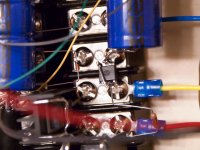
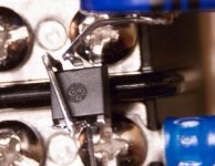
It's not easy to tell the orientation of the device but Only 4 pins should be electrically connected
Well, I am completely stumped.
I traced wiring and found an error with the wiring of the opto, which I corrected. Here is how it is now connected, and is what the Generg-updated schematic stated.
1. Pin 1 to 100R
2. Pin 2 to 0R2
3. Pin 2 to Pin 4
4. Pin 4 to -ve of 1000µF
5. Pin 5 to +ve of 1000µF
But still no go. There appears to be some motor-boating at the speaker output, with DC oscillating between +15 and ??
Do 4N37 work without pin 6 (base) connected ?
Well, I am completely stumped.
I traced wiring and found an error with the wiring of the opto, which I corrected. Here is how it is now connected, and is what the Generg-updated schematic stated.
1. Pin 1 to 100R
2. Pin 2 to 0R2
3. Pin 2 to Pin 4
4. Pin 4 to -ve of 1000µF
5. Pin 5 to +ve of 1000µF
But still no go. There appears to be some motor-boating at the speaker output, with DC oscillating between +15 and ??
The picture looks like 5 pins are connected. Can you take another shot at different angles. EDIT: OK looking at it another time appears I am seeing an illusion.
Do you have a preamp that is DC coupled?
This is important to eliminate the motor-boating (as Nelson previously suggested)
Last edited:
Pin 4 to (-) of 1000 uF cap
Pin 5 to (+) of 1000 uF
Pin 2 connected with pin 4 (is ok) and to midle point 0,2 R and hockey puck
Pin 1 with 100 R is ok.
I have it wired exactly like that now, but still no go....
Attachments
The picture looks like 5 pins are connected. Can you take another shot at different angles
Do you have a preamp that is DC coupled?
This is important to eliminate the motor-boating (as Nelson previously suggested)
I do not have it connected to a preamp, just the input shorted.
Do 4N37 work without pin 6 (base) connected ?
They certainly work in simulation that way
They certainly work in simulation that way
Thx Pico

@ C11 maybe check all other connection ~ make continuity tests specialy this with screws.
Last edited:
Another observation: the bench supplies for the +60 show much less than 1 A being drawn even when motor-boating. This may mean the drive MOSFET is not turning on properly, and no current is flowing. Certainly not 3.2A as per the schematic.
One other thing, I am using a 33000µF output cap since that's what I have on hand. Should make a difference but just in case it does....
One other thing, I am using a 33000µF output cap since that's what I have on hand. Should make a difference but just in case it does....
Thx Pico
@ C11 maybe check all other connection ~ make continuity test specialy this with screws.
Yep, all beeping at they should. Screws are not easy but they do work well when they do.
Yep, all beeping at they should. Screws are not easy but they do work well when they do.
Hope opto are not broken ?
I tested the opto before putting it in, and the diode read 1.06V. A little high but perhaps that's what it should be. I will put in a new one just in case, perhaps tomorrow. But they do not usually fail, do they? For $0.58 each, perhaps I should have reasonable expectations...
If all else fails, I will just wait for the PCBs that Papa mentioned 6L6 is working on ;-)
Don't give up.
Things often become clear after a good sleep.
Is your bias voltage really coming through the transformer windings?
The optocoupler can be damaged when made a wrong connection.
Aha! I will replace it and see if that works. The right way to have done is to through a socket of course, but the socket costs more than the opto!
Thanks for the heads-up.
Don't give up.
Things often become clear after a good sleep.
And 2pD - yes, I will sleep on it!
If all else fails, I will just wait for the PCBs that Papa mentioned 6L6 is working on ;-)
Socket adaptor for ic save opto from too hot pins temperature in soldering process so they are not cook to much.
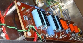
Turrets point to point technique are interesting too( example on photo)
Always more secure to have only soldered connections.
Twice fun debuging and twice joy to be one of first Diyers
Hahahato discover schade feedback vfet simulation in single-ended 50 watts topology from Papa

Attachments
Last edited:
And 2pD - yes, I will sleep on it!
Once you have cracked the puzzle, you might like to solder to these terminal strips, not cheap but not ridiculous expensive either.
Very nice.
More Information Page
Socket adaptor for ic save opto from too hot pins temperature in soldering process so they are not cook to much.
Turrets point to point technique are interesting too( example on photo)
Always more secure to have only soldered connections.
Twice fun debuging and twice joy to be one of first Diyers
to discover schade feedback vfet simulation in single-ended 50 watts topology from Papa
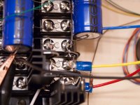
I am using terminal blocks because debugging is easier, and they also fit nicer into their eventual home. Turret boards are wonderful but the last time I had anything to do with them was stringing Black Beauties across them inside a McIntosh MC60. That was a L-O-N-G time ago....So I will start fresh tomorrow with a new 4N37 and do it "nicely". The 1000µF caps I am using are only for verification and getting a better idea for final placement and routing.
I am sure it will be fun when I finally get there, and before I can report on how it sounds, there is still the question as to whether a buffer is needed with my passive preamp.
- Status
- This old topic is closed. If you want to reopen this topic, contact a moderator using the "Report Post" button.
- Home
- Amplifiers
- Pass Labs
- BAF 2015 Coverage