Hi All
A Quick update.")
After some extended listening today with the following config.
R5 220R R6/7 50R R13 200R
I found that with some of my quieter recordings that pot maxing was a little too close for comfort.
So I swapped out R13 to 300R mmmmm much better and from my usual listening pot position of 2-3 o’clock. I now have a pot position 0f 12 o’clock which gives just a little more gain.
So after experimenting a little I’ve ended up with
R5 220 R6/7 50R R13 300R
Pretty much as Calvin recommends way back in this thread.
Nice work.
This Pre is sounding superb and by far the best that I’ve built (and I’ve build quite a few over the years).
Great work guys.
A Quick update.
After some extended listening today with the following config.
R5 220R R6/7 50R R13 200R
I found that with some of my quieter recordings that pot maxing was a little too close for comfort.
So I swapped out R13 to 300R mmmmm much better and from my usual listening pot position of 2-3 o’clock. I now have a pot position 0f 12 o’clock which gives just a little more gain.
So after experimenting a little I’ve ended up with
R5 220 R6/7 50R R13 300R
Pretty much as Calvin recommends way back in this thread.
Nice work.
This Pre is sounding superb and by far the best that I’ve built (and I’ve build quite a few over the years).
Great work guys.
It's a unfortunately you had to have to take apart a 2sj75.
That would be perfect for an aleph j.
Slightly off topic: Could a 2sj75 be even better matched than
2sj109?
Dennis
I believe that having both transistors in the same die is better, so the 2j109 would be the better choice, but the 2j75 is also a good choice.
I have 9 more so I can build quite a few more amps!
Except for leakage current, a capacitor blocks DC.Are you talking about DC voltage or AC? I assume DC blocking. So you are saying that if the capacitor doesn't have to "work" as hard to block DC, it's effect on distortion of the signal is less? In something like the BA-3 where the offset is pretty low (probably less than a volt at all times) it would seem the output cap should have little effect on SQ (other than the value dictating the FR). Correct?
You may insert a DC blocking capacitor where normally no DC difference is present. The DC blocking ability is there for when something goes wrong and DC becomes a problem.
That's the DC part out of the way.
A RC or CR filter has signal voltage across both the R and the C.
In a filter topology the capacitor has an AC or signal voltage across it.
It is in this arrangement that the distortion reports can measure and report the results.
In a coupling type topology, the capacitor is NOT working as a filter. It passes all the wanted signal. The signal voltage across the coupling capacitor is near zero. In such an arrangement there is virtually no distortion of the wanted signal, because there is no signal voltage across the capacitor.
Can you see the three different operating regimes? DC blocking, filtering, coupling.
They are all different in the way the capacitor sees voltage.
Yesterday another Member reported on distortion testing for a ceramic coupling capacitor. He found that instead of using the nearly universally accepted one decade outside the wanted signal passband (as exposed by D.Self for more than 20years, yet still ignored by some), that distortion was virtually zero by using two decades outside the wanted signal passband. It's exactly the same as any other coupling capacitor. Reduce the signal voltage to near zero and the distortion becomes near zero.The message you should be taking is:
minimise the signal voltage and then any capacitor will have virtually no audible effect on the audio signal.
Last edited:
The whole of that argument is based on the capacitor acting as a filter and in that arrangement one looks for a capacitor type that minimises the distortion due to signal voltage across the capacitor.This the article and excerpt I was referring to:
http://linearaudio.nl/sites/lineara...0 to 100uF caps and 100 Hz measurements_0.pdf
"...10 µF choice.
We have three possibilities. A double Bi-polar using two 22 µF 50/63 volt Bi-polar electrolytics, a 10 µF metallised PET or an
assembly of three 3.3 µF PPS capacitors.
The lowest cost solution for use with signal voltages less than 1 volt and no significant bias, is a double Bi-polar series pair.
A 10 µF MMK metallised PET takes the same PCB area and distorts less with DC bias.
The PPS capacitor assembly ensures lower distortion, especially when used with increased AC signals or DC bias voltage.
However it occupies more board area and is expensive.
An assembly of Polypropylene capacitors, as used in the DC bias network, would provide the lowest possible distortion but
requires a five times larger board area and is most expensive.
For small AC signals and modest DC bias, I choose the 10 µF MMK metallised PET capacitor...."
Although in this case the BA3 has a voltage gain of 10 if I am not mistaken, so actually the AC signal will be more than 1 volts i think...
If you are using the capacitor as a coupling capacitor then the whole argument falls apart, because ALL capacitors add virtually no distortion to the wanted signal, if the coupling capacitor has no signal voltage across it.
picking two adjacent "in the die" transistors gives no oportunity to the manufacturer to match device parameters.I believe that having both transistors in the same die is better, so the 2j109 would be the better choice, but the 2j75 is also a good choice.
I have 9 more so I can build quite a few more amps!
Look at the matching specification of the dual 2sk389.
They claim for the pair a tolerance of 10% for the ONE parameter they have specified for.
Have a look at your 2sj109 datasheet, you will see Idss and Yfs as min 0.9 That allows a 10% mismatch even for something a simple to measure as the Idss. I have measured some of my 2sk389 and 2sj109 and they do NOT match for Idss.
Matching (as done on opamps and resistors) is to test for equality of a parameter and then to adjust until that parameter is matched. I don't believe
any manufacturer is claiming to have "matched" parameters when they are using adjacent "in the die" devices.
The BIG advantage of adjacent devices is the very short Thermal Route and this gives similar Tj while in operation, or Thermal tracking of one device by the other. For some applications Tj matching is important.
Last edited:
I'm thinking of using the relaixedpassive relay based stepped attenuator. 27k input impedance and the output impedance varies between 0 and 13k, which will feed the BA3FE.
Are these attenuator values good for the BA3 or should I change the input resistor (or any other resistor for that matter) ?
Are these attenuator values good for the BA3 or should I change the input resistor (or any other resistor for that matter) ?
A conventional vol pot with an input impedance of 27k fed from a source with 1k, will have a maximum output impedance of 1/4*(27k+1k) i.e. <7k
If your vol pot goes as high as 13k for Zout, then they have added another 6k of output resistance for some unknown reason.
A 13k source impedance does no real harm at the power amp input.
The harm has already been done by the cable between the vol pot and the power amp. And exacerbated by the almost mandatory RF filter that should be fitted at the power amp input.
Last edited:
A conventional vol pot with an input impedance of 27k fed from a source with 1k, will have a maximum output impedance of 1/4*(27k+1k) i.e. <7k
If your vol pot goes as high as 13k for Zout, then they have added another 6k of output resistance for some unknown reason.
A 13k source impedance does no real harm at the power amp input.
The harm has already been done by the cable between the vol pot and the power amp. And exacerbated by the almost mandatory RF filter that should be fitted at the power amp input.
The output of the attenuator will be centimetres away from the BA3 FE which will be used as a preamp. The BA3FE has low output impedance to feed an F4 power amp through a low capacitance RCA cable.
A conventional vol pot with an input impedance of 27k fed from a source with 1k, will have a maximum output impedance of 1/4*(27k+1k) i.e. <7k
If your vol pot goes as high as 13k for Zout, then they have added another 6k of output resistance for some unknown reason.
A 13k source impedance does no real harm at the power amp input.
The harm has already been done by the cable between the vol pot and the power amp. And exacerbated by the almost mandatory RF filter that should be fitted at the power amp input.
I don't know how you measured your maximum output impedance. But it is far too high, there's an extra 6k in there that should not be there.I don't understand that, input impedance of 27k is where the sources connect to right? And the Zout of 0 to 13k will connect to the preamp?
But a 27k vol pot should have a maximum output impedance of 1/4 of the 27k.
Check here:
relaixedpassive
"With the attenuator resistor values assigned in the schematics, the attenuator has an input resistance of 27K, and an output resistance that varies between 0 and 13K, depending on the attenuation level. This value is a compromise between wanting a high input impedance (easy to drive by the signal source) and a low output impedance (good to drive the power amplifier). If you would like to change the impedance level (higher or lower) you can find new resistor values with the help of my online attenuator calculator. The current values of this design are indicated near the bottom of that page."
Finished BA3-FE!!!
Finally finished the BA-3FE. What a phenomenal preamp! Wow!
Just wanted to thank everyone in this community for their help. Of course Nelson Pass for this awesome circuit, Jim for the build guide, Salas for all his help with the power supplies, and Marra for the clear pictures I used often as a reference (our preamps are essentially the same).
I started a thread about a year ago asking if I should build a BA-3FE or rebuild the B1 with better parts. The BA3-FE kinda of blows the B1 in the weeds. I'm using the preamp between a Pearl II and F5.
Also, in the meantime I bought (yes I admit it) an all tube preamp that I really love. I've only listened to a few albums so far but the BA-3FE is at least as good as the tube preamp. I haven't really done AB comparisons but the funny thing is I'm hearing more similarities than differences.
Another thing, the BA-3FE doesn't have nearly as much gain as I thought. I find it hard to believe it would drive an F4 in my system.
Again, Thank You
Last edited:
1/2 J75 ???misterious P channel transistor?? Any guesses?
Another thing, the BA-3FE doesn't have nearly as much gain as I thought. I find it hard to believe it would drive an F4 in my system.
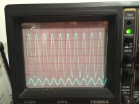
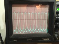
I used a 25K (24 step audio taper) attenuator in my build. I think that's the wrong value because I get to unity gain around step 13.
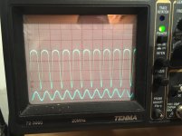
But while testing, putting 1V p-p in, I get 6V p-p out, or ~15db This happens at step 22. At step 23 and 24 the wave starts to clip and voltage goes down.
I wish I could tell you what the resistance is at those steps but I'll need to take the attenuator out of the circuit. Gold point has charts on their website, but I can't make head or tails of it.
Attachments
- Home
- Amplifiers
- Pass Labs
- BA-3 As Preamp