pick your own poison
whatever you do , try MKC ( polycarbonate ) bypass
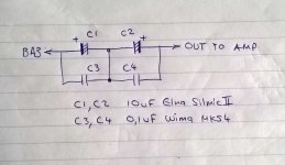
me , as stubborn , will use Elna Silmic + MKC
Zen Mod I was thinking of doing the same Elna Silmic II bypassed by Wima MKS4 that I have laying around.
My question is how would you connect the Elnas? Would you use 2 back to back with their negatives connected? If so what value in order to achieve 10uf in AC? 2x 20uf? I.e. like that below?
---(+)||---||(+)---
Last edited:
I have a long story of measure once, cut once, then go to the store to buy more wood...Now I measure twice!
I know that lesson well!
Russellc
I know that lesson well!
Russellc
Hah! I measure 3 times and cut...only to find I measured incorrectly
all three times.
Dennis
A picture speaks a thousand words...
Is this cheap way to replace the 10uf input cap correct?
C3,4 are optional
Should I increase C1, 2 to 20uf?
Could I use 1 bypass cap across both Elnas?
math says 20uF

The output capacitor pads are marked C3.
One is large enough to hold a big fancy film cap, the other pad, connected in parallel, is for a small 10uF can electrolytic. the electrolytic may be polar, and the small pad is marked for orientation.
The provision for an inexpensive (yet high performance) cap such as a Silmic or audio-grade Nichicon has already been placed on this PCB. You can bypass that with a small value film cap if you wish.
C1 and C2 are part of the bias voltage supply, and have nothing to do with the output signal.
Here’s my attempt at the BA-3 FE as a pre
 [/URL][/IMG]
2x 20V 80VA transformers, Will’s 317/337 reg boards, Alex and Greg’s JLH Ripple eaters.
I’m using stacked relay IP switchers for IP and Ground switching.
BA-3 board uses matched LSK from DIYA store and matched Fairchild mosfets. Resistor value changes: R5 220R R6/7 50R R13 200R. OP cap are Mundorf MKP. All resistors are 1/2W PRP except R13 Mills 5w wire wound.
Volco is a 50K DACT switcher.
P3 is in the central position. I'll have a play with that later
Shamefully everything except the BA-3 is from my parts box hence the large transformers.
Looks so, so but sounds superb
Zen Mod I was thinking of doing the same Elna Silmic II bypassed by Wima MKS4 that I have laying around.
My question is how would you connect the Elnas? Would you use 2 back to back with their negatives connected? If so what value in order to achieve 10uf in AC? 2x 20uf? I.e. like that below?
---(+)||---||(+)---
don't bother with bipolar arrangement , just place single SIlmic and bypass it
Two are better than one.Thanks for the reply. Indeed Nichicon Muse have bipolar elcaps which is an option.
Wouldn't placing one polar electrolytic cap reverse bias it?
This from Bateman 2003 confirms that back to back Bi-polar when used as a filter have significantly less distortion than a single Bi-polar. Another para in the same report confirmed that back to back polar electrolytic are significantly lower distortion than single polar when used as a filter.Two better than one?
I already had some 220mF 63 volt Nitai Bi-polar electrolytics, Farnell 317-4906. Two connected together in series would
approximate 100mF.9 (m in this case is micro. AT edit)
Measured at 0.3 volts with no bias, second harmonic level reduced 6 dB compared to the Panasonic S Bi-polar. With second
and third harmonics buried in the noise floor, distortion at 0.00033% measured the same as the PET assembly.
With 18 volt DC bias, second harmonic measured -105.3 dB and distortion 0.00063%. A near four fold improvement compared
to the Panasonic S Bi-polar, more than seven times better than the best polar capacitor tested.
For coupling duty the distortions are even lower, probably unmeasurable.
Bateman tested this and pooh-poohed the added film capdon't bother with bipolar arrangement , just place single SIlmic and bypass it
This is again based on the test method where the electrolytic is used as a filter.Using a Film Shunt.
Some writers advocate using a low distortion film capacitor in parallel with an electrolytic, to reduce distortion. Does it work ?
To find out I made a few measurements on these capacitors using a 1 volt test signal, unbiased then with 18 volt DC bias. As
shunt I used my low distortion 1mF MKP also a 10mF bank of three 3.3mF low distortion metallised PPS capacitors.
With 1mF shunt, second and third harmonics of the Silmic reduced by just 1 dB. Using the 10mF, both harmonics reduced by a
further 1 dB. This small reduction is not worth the additional PCB space and extra cost, because even with a 10mF shunt,
distortions far exceed those of my metallised PET assembly.
Last edited:
Thank you Andrew, that's very interesting stuff.
It makes sense that a single polarised cap will have more distortion, however I'm not too hung up on distortion - as long as it's low enough.
I am more worried about damaging the resistor with reverse biasing, as well as the sonic qualities. For the latter, I guess there is only one way to find out!
Shamefully everything except the BA-3 is from my parts box hence the large transformers.
Shamefully? Not at all! That makes it so much better a success!!!
Really well done!
This from Bateman 2003 confirms
Bateman 2003 tells you.By the way does anyone know how bipolar elcap are constructed? Are they essentially 2 polar back to back?
Shamefully? Not at all! That makes it so much better a success!!!
Really well done!
Your build guide made it possible
great work.
Bateman 2003 tells you.
Thanks Andrew very interesting read. What I take away from that is... use 2!
- Home
- Amplifiers
- Pass Labs
- BA-3 As Preamp