I don't agree.
All that testing for distortion is when the capacitor is working as a filter. That is the only way they can get sufficient voltage across the capacitor to then be able to measure the voltage.
If the coupling capacitor is working with virtually no signal voltage across it then you will find it virtually impossible to measure any distortion of the wanted signal.
The message you should be taking is:
minimise the signal voltage and then any capacitor will have virtually no audible effect on the audio signal.
I don't agree.
All that testing for distortion is when the capacitor is working as a filter. That is the only way they can get sufficient voltage across the capacitor to then be able to measure the voltage.
If the coupling capacitor is working with virtually no signal voltage across it then you will find it virtually impossible to measure any distortion of the wanted signal.
The message you should be taking is:
minimise the signal voltage and then any capacitor will have virtually no audible effect on the audio signal.
Are you talking about DC voltage or AC? I assume DC blocking. So you are saying that if the capacitor doesn't have to "work" as hard to block DC, it's effect on distortion of the signal is less? In something like the BA-3 where the offset is pretty low (probably less than a volt at all times) it would seem the output cap should have little effect on SQ (other than the value dictating the FR). Correct?
This the article and excerpt I was referring to:
http://linearaudio.nl/sites/lineara...0 to 100uF caps and 100 Hz measurements_0.pdf
"...10 µF choice.
We have three possibilities. A double Bi-polar using two 22 µF 50/63 volt Bi-polar electrolytics, a 10 µF metallised PET or an
assembly of three 3.3 µF PPS capacitors.
The lowest cost solution for use with signal voltages less than 1 volt and no significant bias, is a double Bi-polar series pair.
A 10 µF MMK metallised PET takes the same PCB area and distorts less with DC bias.
The PPS capacitor assembly ensures lower distortion, especially when used with increased AC signals or DC bias voltage.
However it occupies more board area and is expensive.
An assembly of Polypropylene capacitors, as used in the DC bias network, would provide the lowest possible distortion but
requires a five times larger board area and is most expensive.
For small AC signals and modest DC bias, I choose the 10 µF MMK metallised PET capacitor...."
Although in this case the BA3 has a voltage gain of 10 if I am not mistaken, so actually the AC signal will be more than 1 volts i think...
Last edited:
And this:
http://linearaudio.nl/sites/lineara... 12 2002 mar2003 1uF electrolytic or film.pdf
"...At 1 volt AC, regardless of bias voltage, the single polar capacitor and the back to back pair both produced visible
intermodulation.
With 30 volt DC bias, second harmonic distortion for both the single polar capacitor and the back to back pair measured -86
dB. Both styles produced intermodulation and similar harmonic distortions, measuring 0.00461% and 0.00472% respectively.
More than double that found with the Bi-polar. see Fig. 10/12B
In every distortion test, the Bi-polar capacitor produced much lower distortions than were measured on similar value and
voltage polar capacitors...."
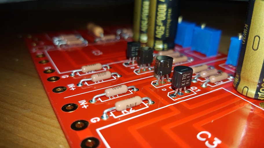
misterious P channel transistor?? Any guesses?
LSJ74?
LSJ74?
Those have markings written on them. Any other guesses?

Those have markings written on them. Any other guesses?
Every JFET i have ever purchased had markings on them, I have never seen one without them. Is that a Portuguese innovation?

Anyway, my guess is either Fairchild J174 or J175. However, I own several of each and they do have markings.
Last edited:
2SJ75 cut in half.
Winner Winner, chicken dinner!!
I have some 2sj74 but they're all above 7.5-8mA idss. I wanted to use a bit lower Idss because the rails will be +-32V. Dissipation will be around 200mW which should be good to keep them working for a long time! And with some small heatsinks I shouldn't have to worry for a long time!
Last edited:
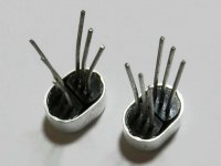
Now these will probably be all gone by the time you read this:
B+D Enterprises - Search results for: '2SJ75'
Disclaimer: I do not know if these are genuine but it's hard(er) to fake with the metal cap and all
B+D Enterprises - Search results for: '2SJ75'
Disclaimer: I do not know if these are genuine but it's hard(er) to fake with the metal cap and all
Did you actually have to cut it in half or just remove them from the metal can?
You have to cut the side of the metal can, it's quite easy as it is a very soft metal, I did it with a very small wire cutter I use for clipping leads. Make a small incision and then use a needle nose plier to pull the metal away.
- Home
- Amplifiers
- Pass Labs
- BA-3 As Preamp