My personnal Supercharged output power and thermal issues
My " L " shape adaptor is no good:
YouTube - Amplifier - My Supercharged thermal issue, the L adaptor
regards,
Carlos
My " L " shape adaptor is no good:
YouTube - Amplifier - My Supercharged thermal issue, the L adaptor
regards,
Carlos
Newton, a brazilian friend has build the Supercharged
And here you have a sample:
YouTube - Teste do DX Supercharged com uma fonte de 43 Volts
regards,
Carlos
And here you have a sample:
YouTube - Teste do DX Supercharged com uma fonte de 43 Volts
regards,
Carlos
Supercharged kicking hard those speakers
http://www.youtube.com/watch?v=SA1AC7uBj4k&feature=mfu_in_order&list=UL
enjoy,
regards,
Carlos
http://www.youtube.com/watch?v=SA1AC7uBj4k&feature=mfu_in_order&list=UL
enjoy,
regards,
Carlos
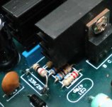
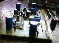
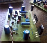
Supercharged blue boards already have higher watt resistances in the
rails....so, main change is to use MJE15032 in Q6 place and the use of heatsink for both VAS transistors.
Watch the picture....i had mo high watt resistance to use...you see 1/4 watt unit
regards,
Carlos
rails....so, main change is to use MJE15032 in Q6 place and the use of heatsink for both VAS transistors.
Watch the picture....i had mo high watt resistance to use...you see 1/4 watt unit
regards,
Carlos
Attachments
Last updates about the Dx Blame MKII Supercharged
using blue boards.
Some Dx stuff, some Dx Supercharged update and news:
YouTube - Dx stuff and Dx Blame MKII Supercharged last update
regards,
Carlos
using blue boards.
Some Dx stuff, some Dx Supercharged update and news:
YouTube - Dx stuff and Dx Blame MKII Supercharged last update
regards,
Carlos
The second half part of this video is about the last Dx Blame Supercharged update
informations.
This was posted in the signature line, but i do think some guys does not even perceive that signature below our posts....here is the link:
YouTube - Dx stuff and Dx Blame MKII Supercharged last update
regards,
Carlos
informations.
This was posted in the signature line, but i do think some guys does not even perceive that signature below our posts....here is the link:
YouTube - Dx stuff and Dx Blame MKII Supercharged last update
regards,
Carlos
A friend made some tests while the amplifier was clipping
Usually, the Supercharged can pump out more than 150 watts rms in 8 ohms and twice of that in 4 ohms aproximatelly...but if you tollerate some distortion and even clipping, it can produce much more than that.
Video is in portuguese, but electronics are international language...there's a sinusoidal generator in 1 kilohertz, a yellow meter show milivolts peak entering the power amplifier, the gray meter shows output voltage, rms voltage over a 5 ohms resistive load and Casio calculator gives you power.
My friend is not monitoring the waveform, of course it will be clipping above 35 volts, but this shows how much power you can drain from the unit.... also modern music already have some clipping containt in it's waveform, in special guitar is distorted.... some guys tollerates these crazy levels of clipping, and during peaks you can see how much power it can send to the load.
The amplifier is rated, conservativelly, at 100 watts 8 ohms and almost twice of that at 4 ohms, when distortion is around 0.003 percent (THD).... above this level you may have 160 and 330 watts reaching 1 percent...and higher of course will reach 5 percent or even more.
Because i already knew some guys would force the amplifier above it's limits, i have created the Dx Blame MKIII Supercharged that will be produced (boards) in another forum as i am in activity in 8 international foruns.... Meanman will distribute them in Europe near future...it uses three output pairs..exactly to turn the unit stronger to face abuses.
Soon you gonna have MAKO, this one will use 10 output pairs and 500 watt undistorted at 4 ohms...imagine that MAKO overdriven in the same way the MKII was forced above it's limits!.....maybe MAKO will have more than 10 pairs.... i am testing it to deliver in a couple of monthes.
Here is the video:
YouTube - Teste_Supercharged.AVI
regards,
Carlos
Yes.... maximum resistance, in our case, means smaller possible adjustable ....
... stand by current, the iddle current, also called bias in a generic way.
Usually, to the Supercharged, we have around 930 ohms from base to emitter.... so, this will help you to adjust... adding both resistances, the fixed one plus the variable...if needed, then replace the bias trimpot using 1K in the place of 500 ohms....but usually the original solution works.
Depending your heatsink, would be a good idea to reduce current as much as you can to avoid too much heat, controling this way, not only the stand by current but also dinamically the operational current when the amplifier operates.... check milivolts over your emitter resistance and divide it by your emitter resistance.
I think you know, but there are always beginner reading threads.... 1 milivolt reading (0.001V) over 0.22 ohms power transistors emitter resistances, means 4.5 miliamperes aproximatelly (0.0045A)... and this multiplied by the supply voltage (Power is voltage multiplied by current) means 0.247W to each power transistor...less than 1 watt waste and you will have the guarantee that all them will be operating....will be as cold while operating as possible adjusting this way.
If people decide to use 0.47 ohms, then 1 milivolt will represent less current to each power transistor... and the amplifier will be more and more dead cold when iddle.
I hate heat, reason why i cannot tollerate class A anyway.....and i do all i can to avoid it.... to my feelings, amplifier case hot to the touch is reason for panic and to call fire squadron!
Have you watched this video?
YouTube - Teste_Supercharged.AVI
regards,
Carlos
This one is interesting too.
YouTube - Teste do DX Supercharged com uma fonte de 43 Volts
Another one from Newton Costa:
YouTube - DX SC fonte 43 Volts
In the reality, the amplifier cannot put out all that power measured by Newton (last video published in the previous post) using generator, multimeters and dummy load..because he was not monitoring the clipping.... his multimeter was measuring wrong frequency as these multimeters are precise only with 60 hertz, sinusoidal waves...not good for 1000 hertz and not precise with square waves.
Square waves are not good music...hardly clipped....the amplifier can put out a lot of distortion saturanting this way...real world is 150/300 watts...and very low distortion is 100/200 watts...the rest is distortion, clipping, DC containt in the waveform..not real, nor precise....his video was good to show the amplifier is huge...but that sound in that level of clipping, for sure was not nice.
regards,
Carlos
Last edited:
DX MKII Supercharge Complete......
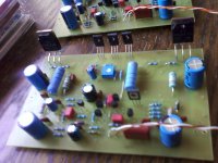
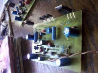
Hello Uncle Charlie......
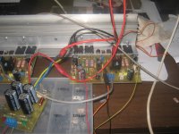
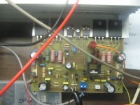
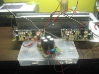
I read from your other thread that your health is not very good.....hope you get well very soon..... I completed my DX MKII supercharged last night.....both channels are working fine and the sound is as always very good......thanks once more for a very good amplifier..... I have a question about one of my channels. I switch on the amp......everything is ok. When i measure dc offset on output I get 200mV on the output. This is a bit high. Now I try to set up bias current. I removed the fuse on the positive rail, put my volt meter over the 100R resistor. Switch the amp on and try to set the current with trimpot....The lowest reading that I can set the pot is around 6 to 7 volts. This tells me that the lowest idle current this channel can have is I=V/R, around 60mA. Is this ok. When I connect a sound source the output transistors gets very hot compared to the other channel........Just two questions....
1) what can I do to decrease my dc offset voltage on output. First channel is -60mV compared to second channel that is 200mV.
2) what is bias current across 100R resistor in rails.
Here is a pic of my setup. Will post more pics when I am completed.
Once again .......thanks for the design and help.....hope you get well soon.
Regards,
MACD
Hello Uncle Charlie......
I read from your other thread that your health is not very good.....hope you get well very soon..... I completed my DX MKII supercharged last night.....both channels are working fine and the sound is as always very good......thanks once more for a very good amplifier.....
I have a question about one of my channels. I switch on the amp......everything is ok. When i measure dc offset on output I get 200mV on the output. This is a bit high. Now I try to set up bias current. I removed the fuse on the positive rail, put my volt meter over the 100R resistor. Switch the amp on and try to set the current with trimpot....The lowest reading that I can set the pot is around 6 to 7 volts. This tells me that the lowest idle current this channel can have is I=V/R, around 60mA. Is this ok. When I connect a sound source the output transistors gets very hot compared to the other channel........Just two questions....1) what can I do to decrease my dc offset voltage on output. First channel is -60mV compared to second channel that is 200mV.
2) what is bias current across 100R resistor in rails.
Here is a pic of my setup. Will post more pics when I am completed.
Once again .......thanks for the design and help.....hope you get well soon.
Regards,
MACD
Attachments
Hello Macd, thank you by your usual confidence and kindness with me
Well, stones inside my left kidney are something usual...happens from time to time.... each 10 years i use to spell them with a lot of pain... a genetic problem, a family problem.... i accept this and i use injections into myself to control the pain and go waiting the system to spell it out.
Thank you Macd by your interest in uncle charlie's health.
Increasing the resistance from base to emitter in the bias control stage will fix the whole thing...the bigger the resistance from base to emitter the smaller will be the stand by current.
if you are using " L " shape adaptors, and if you think it is not good (I had that trouble before) then reduce your current reading milivolts (Dc) over the power emitter resistances..adjust to read 500 microvolts to 1 milivolts there, this way your amplifier will work fine and cold.
Some guys uses 5 to 7 volts...they feel this better in sonics... i could not perceive that advantage and i hate heat, unaceptable to me in special if heat appears during stand by... my personnal aversion goes to heat.. the waste this represents, waste of energy, the changes in the transistor parameters, the risk of thermal drift.... the fear i have about heat... this way, my amplifiers are usually dead cold during stand by mode..and this changes a lot it's dinamic behavior related heat too.
Currents adjusted to 25 miliamperes each rail works fine too, this is what results when we reduce the stand by current monitoring current developed over (voltage drop) the resistances we have in the power output stage..and the small voltage drop represents very small iddle current to each power transistor.... as 1 milivolts results in 4.5 miliamperes circulating from colector to emitter in each power transistor, this means a fourth of watt to each one of them... 1 watt total heat generated in the power output in stand by mode.
If you have good, and real flat, " L " shape adaptors, or a flange in your heatsink, or if you are installing your power transistors directly into the heatsink, then you can play with stand by current searching for the point you believe and feel as better...i do think if you increase too much, let's say 200 or 3 hundred miliamperes, you will loose details, low level details and something will appear muffled..but this is personnal opinion...others disagree...there are controversies on that and i really think you should check this by yourself to decide what you like the most.
Off set seems huge...you may have mistakes in your circuit...for sure you have.... usually does not go above 10 milivolts.... so, check it twice, three or four times because you really have something strange on that.... check your supply, sometimes your positive voltage is really different (huge differences) compared to the negative rail voltage... rail resistances wrong.... well... something may be strange.
If you want, you can artificially change this tweaking the input current sink resistances... tweak R8 or R9 installing resistances in parallel.... try 2K2 and then increase and decrease in order to reduce your off set....but will not be easy, as you have something wrong in your circuit... a small mistake i think.... and you gonna find it....if installing paralel resistance the problem gets worse, then try the other resistance or stop to install parallel units and then go thinking to increase the resistance value installing a small value trimpot (50 ohms) in series with R8 or R9 in order to decrease your off set.... you know, i have assembled 10 units, 10 channels here...and no one show big off set.... this makes me believe you may have a mistake in your boards my dear friend.
There are several videos in my Youtube channel, and about the Supercharged you have more than 50 videos...please, visit the channel and take a look:
http://www.youtube.com/user/destroyersoueu
This one talks about heatsinks for VAS transistors:
http://www.youtube.com/watch?v=LFGn1BFcJLE
And there are other videos explaining how the amplifier operates in details too...also about adjustments and about heatsink issues (the " L " shape adaptor issue)
http://www.youtube.com/watch?v=NchtCdxD5XM
http://www.youtube.com/watch?v=0lvs65yDmag
Do not worry, audio is in portuguese and also you will have comments in english too.
regards,
Carlos
Last edited:
Thanks Uncle Charlie... will do this test tonight.....will let you know. I will also watch your videos on youtube for more details. Maybe I am missing something. Should I install any jumper wires in C25 and C21 positions on PCB. I am not using this caps in the supercharge version.
Regards,
MACD
Regards,
MACD
Better not to install jumpers in C21 and C25 positions
We provide room for these capacitors in order to allow users to assemble the Dx Blame ES model, as it uses these capacitors...let these holes empty to avoid shorts.
These capacitors have influence in sonics, they will not fix off set or stand by current.
regards,
Carlos
We provide room for these capacitors in order to allow users to assemble the Dx Blame ES model, as it uses these capacitors...let these holes empty to avoid shorts.
These capacitors have influence in sonics, they will not fix off set or stand by current.
regards,
Carlos
hello Uncle Charlie,
I did some mods last night with no success. I replace R20 with 680R and changed bias pot to 1K. Now I can set my bias current a bit lower but only to 5mV on the positive power transistors and I think my negative power transistors are in the uV region. I cannot measure this because my volt meter only goes to mV range. DC offset is still 200mV. I double checked everything. I compared every resistor value with my working channel and is exactly the same. Checked for shorts, nothing. The amp is playing lovely sound. Crystal clear. No excessive heat generated. My positive output transistors gets a bit warmer then negative but I think this is because output bias current is different. I think maybe my power output transistors are fake. Maybe I need to matched them before installing them. What do you think? How can I matched my output transistors?
Thanks,
MACD
I see what you found dear Macd...but for sure, you still have a mistake
In your circuit...if you love the sonics is because you are generating second harmonics because of the mismatch you have.
I suggest you to continue to search for errors....no doubts that you still have a mistake, the amplifier behavior is not fine...it is absolutelly symetrical in the voltage into the drivers and output...means if you have 531 mV in the power output, the NPN one..you will have 531 mV or something within 20 percent in the PNP counterpart....also this happens to the drivers and you must be able to reduce much more your stand by current.
Check the bias control transistor and replace it to a BD139..... there you have 2.4 volts from colector to emitter and you need a NPN transistor..almost all transistors ever made, of course silicon transistors, will fit...others, sometimes, have different pin configuration... Rudi found one that has B,C,E inverted related the needed pin configuration to match the pcboard...this happens, and the circuit may operate (badly) with the inverted bias transistor.
In the reality, my dear friend, if you fix the whole thing you may have worse sound compared to the sonics you have, dispite you are having a dirty sonics because of "more" switching power, as a half of your amplifier is switching more than the other half cicle...you are having switching on and switching of, when you can have only switching off.... we adjust the units to be on (some current crossing colector to emitter).... the assymetrical sittuation changes the harmonic distributions and may produce such kind of nice sound some guys loves....but you should try, and listen with your amplifier operating perfectly, in order to allow you to compare...this is my suggestion..to continue to search for errors..i am absolutelly sure there are errors..one or more....and it is normal, common, standard, to produce mistakes and to watch them without see them..this is very normal..we humans are this way..we fail a lot...and our biggest failure is to believe we do not produce mistakes, what is in the main trouble...that belief does not let us search things with confidence..our eyes passes over inverted transistors without see them... we go checking.... we say yes and the mistake remains.
As a said before, i hope you believe in uncle charlie, this behavior is not normal, not standard, not common...this never happened here when building these amplifiers...so..there's something wrong on your unit....... or i have made 20 amplifiers producing the "fixing mistake" that made everything fine or your unit has a mistake because is showing strange signs.... seems to me i have better chances, because to produce 30 boards with the SAME mistake that made the amplifier stable (and hundreds of others made the SAME mistake i did)...or the mistake is in your amplifiers... statistically, it is more possible you have the mistake....you know... "fixing mistake" is because i am understanding the schematic is wrong..that you have build it fine and we all have made mistakes....funny, not very possible...but not impossible....just difficult to happens...everybody wrong, resulting perfect amplifier and you rigth resulting a non perfect amplifier....there are logic problem on that.
regards,
Carlos
Last edited:
Yes you are write Uncle Charlie.........I will still continue with fault finding.....I will test the transistors today....maybe there is a faulty transistor.....will keep you posted....can you post final schematic of Supercharged with all mods please.......want to compare with my schematic. I might have missed something...
Regards,
Macd
Regards,
Macd
- Status
- This old topic is closed. If you want to reopen this topic, contact a moderator using the "Report Post" button.
- Home
- Amplifiers
- Solid State
- Are you ready to face strong emotions?.. Dx Blame MKII and the Supercharged release!