I like the way you have used the "area" under the output devices to run the various traces.
I like the much closer spacing of the +ve, -ve and Pground.
I wonder if radial emitter resistors would reduce the PCB width and output device spacing even more?
I do not like the feedback tapping off the wrong end of the output rail.
This has the potential to become a smaller and better performing PCB.
Wonderful pcb.
A possible solution is moving the point where the output is taken to the point where the feedback is taken. Then use the resistor-coil combo at the output to take the output to the right side of the pcb again.
I believe with a bit of pcb-trickery this can be done.
Regards,
Klaas
Plenty of possibilities with this layout to shorten the gnd-return even further.I like the way you have used the "area" under the output devices to run the various traces.
I like the much closer spacing of the +ve, -ve and Pground.
I wonder if radial emitter resistors would reduce the PCB width and output device spacing even more?
+1.I do not like the feedback tapping off the wrong end of the output rail.
This has the potential to become a smaller and better performing PCB.
A possible solution is moving the point where the output is taken to the point where the feedback is taken. Then use the resistor-coil combo at the output to take the output to the right side of the pcb again.
I believe with a bit of pcb-trickery this can be done.
Regards,
Klaas
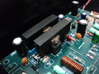
The L//R part of the Thiele Network does not need to be on the PCB.
I believe it is better to locate the L and it's magnetic field away from the PCB and away from the metal chassis panels.
The first Zobel part (R+C) should be located very close to the output devices to minimise inductance in the HF return route.
I believe it is better to locate the L and it's magnetic field away from the PCB and away from the metal chassis panels.
The first Zobel part (R+C) should be located very close to the output devices to minimise inductance in the HF return route.
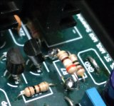
What are the advantages (disadvantages) of those 1N4007 paralleled with OPs?
They do not appear in the original schematics.
Consider the reverse biased diode at a relay coil. The speaker is a much larger coil (back EMF). The 2 diodes shunt this EMF to the rails , sparing your outputs the abuse. Fast switching , 3 amp diodes are good for this purpose.
")
OS
Hi, Max.
As OS said... in my boards I used 1N4007 near Collector-Emitter outputs pins.
See photos in these posts:
http://www.diyaudio.com/forums/solid-state/164066-dx-blame-st-builders-thread-post-pictures-reviews-comments-here-please.html#post2135297
http://www.diyaudio.com/forums/solid-state/164066-dx-blame-st-builders-thread-post-pictures-reviews-comments-here-please-7.html#post2180868
http://www.diyaudio.com/forums/solid-state/164066-dx-blame-st-builders-thread-post-pictures-reviews-comments-here-please-8.html#post2193401
Regards
Consider the reverse biased diode at a relay coil. The speaker is a much larger coil (back EMF). The 2 diodes shunt this EMF to the rails , sparing your outputs the abuse. Fast switching , 3 amp diodes are good for this purpose.
OS
As OS said... in my boards I used 1N4007 near Collector-Emitter outputs pins.
See photos in these posts:
http://www.diyaudio.com/forums/solid-state/164066-dx-blame-st-builders-thread-post-pictures-reviews-comments-here-please.html#post2135297
http://www.diyaudio.com/forums/solid-state/164066-dx-blame-st-builders-thread-post-pictures-reviews-comments-here-please-7.html#post2180868
http://www.diyaudio.com/forums/solid-state/164066-dx-blame-st-builders-thread-post-pictures-reviews-comments-here-please-8.html#post2193401
Regards
Last edited:
Looks nice.
Does anyone have a link for the enameled wire for making the inductor, I can't find the stuff anywhere on Digikey and I've tried searching other suppliers without luck.
Hi Luke
Your in Brisbane right. I got mine from RS Components.
RS Australia | World Leading Distributor of Electronics, Electromechanical and Industrial Components Your search for enamelled wire
Their trade desk is at Archerfield or can order online. Or alternatively you can come round my place and I can give you some I have spare. I may be out of the way though situated between Beaudesert and Browns Plains.
Regards
Simon
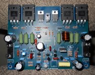
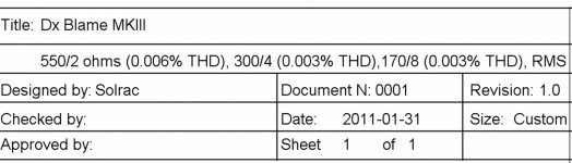
Dx Blame MKIII was produced, assembled and tested
Brazilians asked a higher power version able to operate 2 ohms.
Now 2 beta testers are building....it is the Supercharged retuned....so, not a new amplifier....it is the same having 6 resistances substituted and more output pairs.
regards,
Carlos
Brazilians asked a higher power version able to operate 2 ohms.
Now 2 beta testers are building....it is the Supercharged retuned....so, not a new amplifier....it is the same having 6 resistances substituted and more output pairs.
regards,
Carlos
Attachments
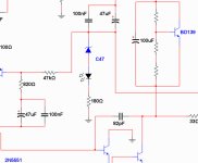
This is a threshold of clipping indicator...it indicates already clipped voltage
that will appear at your Supercharged output when you overdrive it.
Led will have normal brigthness when you reach 156 watts RMS over 8 ohms or twice of that at 4 ohms...the distortion will be around 1 percent when you perceive it on.
Simple, fast to produce and cheap...can be connected into your output terminals or even inside a speaker.
So, the very good idea is to keep it off... when you have clipping you will have high frequency harmonics that may destroy your tweeters..so... adjust your listening level keeping that LED off.
This was made to the Supercharged..when powered by 55 volts supplies..do not use it with higher power amplifiers or you may damage the LED because of overcurrent...works to the Supercharged..was tested...passed!
regards,
Carlos
Attachments
To the ones understand latine languages..here you have a video
explaining more details:
YouTube - Clipping threshold indicator
regards,
Carlos
explaining more details:
YouTube - Clipping threshold indicator
regards,
Carlos
Hi Luke
Your in Brisbane right. I got mine from RS Components.
RS Australia | World Leading Distributor of Electronics, Electromechanical and Industrial Components Your search for enamelled wire
Their trade desk is at Archerfield or can order online. Or alternatively you can come round my place and I can give you some I have spare. I may be out of the way though situated between Beaudesert and Browns Plains.
Regards
Simon
Thanks, I ended up dropping into the local Jaycar yesterday and they had some, I hadn't checked earlier because it didn't come up in there online search. Goes to show sometimes it pays to visit.
Last edited:
Boys, please, use heatsinks to both VAS transistors and use
Big transistors in this position.... something alike MJE15032 is fine.
If you want to push above the limits you can increase the Supercharged sensitivity replacing R7.....try 390 ohms.
Was tested full power over 4 ohms speakers, both channels operating into clipping.
Video about this same subject:
http://www.youtube.com/watch?v=LFGn1BFcJLE
regards,
Carlos
URL=http://img543.imageshack.us/i/stillwaitingknobsarrive.jpg/]
An externally hosted image should be here but it was not working when we last tested it.
[/URL]Attachments
Last edited:
- Status
- This old topic is closed. If you want to reopen this topic, contact a moderator using the "Report Post" button.
- Home
- Amplifiers
- Solid State
- Are you ready to face strong emotions?.. Dx Blame MKII and the Supercharged release!