Simon's power supply is like PORN
Sort of gives you ideas for future encounters with the soldering iron
Got my case ready, traffo's and bridges bolted down just some caps to add and then the nerve to switch it on is all I need.
To Gonethesame - I don't know the answer to your question - sorry
Simon or Walter or even Martin Clark, if he's around, may know however.
Try it - it'll may be good or bad ( that's no help at all !! )
Andrew
Grounding's not something I'm comfortable giving specific advice on to be honest. I know some general principles but connecting the DAC's ground to some other star, I dunno. If it causes a loop that could be a bad thing or just reduce impedance and be a good thing. Then again, cutting the other ground and implementing the new one could be an improvement, or not. I'm not qualified to say, maybe Martin can help.
Simon
Simon
Simon's power supply is like PORN
Sort of gives you ideas for future encounters with the soldering iron
Got my case ready, traffo's and bridges bolted down just some caps to add and then the nerve to switch it on is all I need.
To Gonethesame - I don't know the answer to your question - sorry
Simon or Walter or even Martin Clark, if he's around, may know however.
Try it - it'll may be good or bad ( that's no help at all !! )
Andrew
never mind, i misunderstood a lil...
Grounding
The grounding change you suggest should not cause any harm, so it falls into the try it out and see category of experiment.
EcDesign recommends having nothing on the tda1541a decoupling ground but the decoupling caps. This is a mod I have not yet done. It will require some careful analysis of the arcam pcb to understand if you isolate the decoupling ground without breaking some other part of the circuit. He has developed a list of must do mantras that rank with DEM reclocking, super regs etc. I suspect it is worth while.
Hi ,
Andrew, will linking tda ground to my PS star earth will bring something battah to sound? (moding at my knowleges rythm)
The grounding change you suggest should not cause any harm, so it falls into the try it out and see category of experiment.
EcDesign recommends having nothing on the tda1541a decoupling ground but the decoupling caps. This is a mod I have not yet done. It will require some careful analysis of the arcam pcb to understand if you isolate the decoupling ground without breaking some other part of the circuit. He has developed a list of must do mantras that rank with DEM reclocking, super regs etc. I suspect it is worth while.
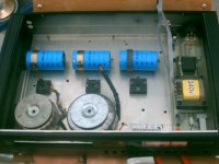
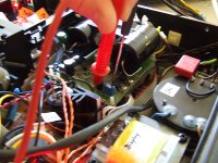
Here's pic of where I was with the offboard ps.
Most of it is bolted down and some wiring is now in - traff's power up and the caps are giving me the DC I need - result.
Just need some military style multi pin sockets and plugs to try it all out.
I guess you can see what I'm planning - powering the whole player from the box you see - which will be underneath the main case.
The player will be switched on / off from this case also.
Have a flat 2mm piece of plastic to fit over the facia hiding the holes left over form the time when it was a CD Player - A bit of acrylic silk black spray paint and you'll never know what it was before - hopefully
The only traff that will remain in the main player will be for the the clock.
It won't be straight forward - nothing is so I'm taking my time and drawing wiring routes and working out how to achieve low impedance at both ends of the cabling - as per AndrewT's explanation in a recently received PM - very helpful man indeed.
More pics to come
Walter - PM sent re valve stage
Andre
I guess you can see what I'm planning - powering the whole player from the box you see - which will be underneath the main case.
More pics to come
Andre
Keep the pics coming as it takes shape. I recognize the box from its previous duty as an Arcam CD. Cool idea as it will match the cd player it powers.
You will have room in the box in case you develop an interest in adding chokes to your power supplies.
Ok, I did a very nice little tweak today. This one is thanks to Lee (Thomo), who spotted an opportunity to hugely improve the Pass D1 output stage for almost no money. These are the best tweaks: low cost, big gains, quite easy to implement. Lee already tried adding this CCS to the circuit and reported good improvements and even sent me the FETs to do it, so I had to! Basically the FET is dropped in, in place of a resistor that comes off the -30V PSU rail, with two legs (pins 2,3) tied to -30V and pin 1 to the input side of where the resistor was.
Attachments
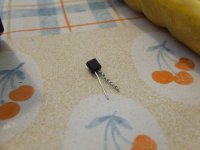
The sound is considerably more detailed and pleasant with the Constant Current Source in-circuit. I don't know how it works but Lee tells me it reduces PSU noise on the circuit. This is after a huge CRLC filter and S Power regulation lol. I am very happy with this. More to come soon I hope.
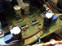
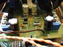
This pic shows adjusting the trimpot to remove DC offset from the circuit's input.
This pic shows adjusting the trimpot to remove DC offset from the circuit's input.
Attachments
H Simon,
Thanks for creating this thread inspired, I took the board out of my Alpha+ last night to take a look at the layout vs the schematic and draw up a list of parts. Not only is the cap missing from the schematic but it seems to be missing from the pcb too ! I can't understand why, perhaps it was just a mistake on the schematic that wasn't picked up on the layout ?
It's a shame they didn't spend a bit more money and use a groundplane (the same is true of the Alpha 5 DAC pcb too).
Jon
Thanks for creating this thread
inspired, I took the board out of my Alpha+ last night to take a look at the layout vs the schematic and draw up a list of parts. Not only is the cap missing from the schematic but it seems to be missing from the pcb too ! I can't understand why, perhaps it was just a mistake on the schematic that wasn't picked up on the layout ?It's a shame they didn't spend a bit more money and use a groundplane (the same is true of the Alpha 5 DAC pcb too).
Jon
Adding CCS to simple followers like that basically stops the current through the pass device varying with the signal applied to it. This improves distortion performance significantly, and that's why it sounds better - not simply a power supply issue at all!
No there is no cap on the Arcam -5v supply so add one, tight to the dac, to its analogue 0v ground. Try 0.1uF film cap or 10uF oscon for a start. Having decoupling caps on the output of the reg is the wrong place as I keep saying
(because it takes the HF decoupling loop from the chip's power pin all the way back to the reg and then to local 0v wherever the reg connects to ground, then back to 0v at teh chip = f'ing useless at frequencies of interest. Keep decoupling loops SMALL. This means, if you are using '3pin-reg replacement' style aftermarket regulators which have a 0v pin you will only get the real benefit of their pefotmance by connecting that 0v pin to the 0v of the load they power - right at teh chip if need be- and NOT where the reg was originally located several miles away.
Minimising that excess shared trace impedance and large loop area really, really matters)
Last edited:
Jon, I'm glad some good has come from creating the thread and you're obviously keen-eyed and methodical. I wonder what else you'll spot!
Martin, that's fascinating about the CCS. With regards to the cap being missing, there is a subtlety you might've missed. There IS a cap, it is next to the DAC chip (usual elco + ceramic arrangement). There is simply not an EXTRA cap, next to the reg, which is present on the other three regulators (though on two it may serve as an input cap for the reg it feeds).
Given what you've repeatedly said about decoupling arrangements and loops I'd like to move my regs closer to the consumers but it's easier said than done, and a joke if you have those huge shunt regs!!
Simon
- Status
- This old topic is closed. If you want to reopen this topic, contact a moderator using the "Report Post" button.
- Home
- Source & Line
- Digital Source
- Arcam Alpha mods