Is VCarve Pro 3D capable?
To do what I did with my baffles you'll need a full 3D capable CAM package.
Don't forget your feeds and speeds. Say you are cutting at 1000mm/min - you'll want to engage at 500mm/min, and rapid (in air) at 2000+mm/min.
If you can, set a Z height clearance plane, say 10mm above the part.
To do what I did with my baffles you'll need a full 3D capable CAM package.
Don't forget your feeds and speeds. Say you are cutting at 1000mm/min - you'll want to engage at 500mm/min, and rapid (in air) at 2000+mm/min.
If you can, set a Z height clearance plane, say 10mm above the part.
Attachments
I'm not sure now that you ask. I had assumed so but looking over the specs it isn't 100% clear. Vectric Cut3D is half the price and definitely does 3D.
Cut 3D - Quick Easy CNC Machining
Cut 3D - Quick Easy CNC Machining
John - I would be very interested to hear how you get on with the spindle.
Ant - you mention "roughing and finish cuts". Unless you only ever intend to do 2.5D cutting, I'd start with looking at simpler 2D cutting of shapes out of sheets (with possibly drilling and pocketing). Machining complex surfaces with multiple roughing and finishing passes takes hours, and maybe isn't the easiest way to learn a machine or software.
VCarve Pro is very clever - essentially it's a signmaking and engraving package. If you think about using a v cutter (one that tapers down to a point), you can cut simple v grooves in material. The width and depth of the groove is controlled by the depth of the cut (you can of course get v cutters with different angles of v, to get deeper+thinner or wider+shallower cuts though).
VCarve varies the cutting depth to create deeper areas, and rises up out of the material to hone fine points in an engraving. Think of the complex carved serifs on fonts like Times - VCarve can do that.
I believe it can also take an image, and based on the widths of lines or density of colour, vary the depth of cut to create impressive 'carved' versions of pictures.
It's very cool, though pretty pricey (for a DIY'er). If I were doing signs on a commericial basis I reckon you could make back the cost very quickly, but for cutting speaker boxes or even milling curved baffles, it's not really what you need.
I really do like SolidCAM. I've been messing around with 3D milling and it seems very easy to use. In fact its so easy that I feel like I'm cheating and it should be much harder! Maybe I'm doing something wrong but it seems as simple as defining your model and then selecting the working area within that model and afterwards picking the type of operation you'd like to do on the working area ie. roughing out material or finishing. After that you click ok and it calculates all the toolpaths.
Couple of things I'm not sure about is the step over rate and tool type to get the best finish.
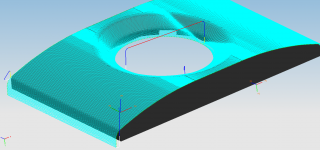
For the step down on roughing I'm using a contour pattern with a 5mm step down and a straight cutter. And for finishing I'm using a linear pattern with a 0.5mm step over and bull nose cutter. Is this even remotely correct? I came to those value with 'educated' guesswork aka. I didn't have a clue at the time
Couple of things I'm not sure about is the step over rate and tool type to get the best finish.
For the step down on roughing I'm using a contour pattern with a 5mm step down and a straight cutter. And for finishing I'm using a linear pattern with a 0.5mm step over and bull nose cutter. Is this even remotely correct? I came to those value with 'educated' guesswork aka. I didn't have a clue at the time
50% stepover for roughing.
Tweak it to get about 0.5-1mm stepover for finishing a 3D part, and use as big a tool as you can.
Or you might be able to specify a scallop height - say 0.2mm, and have it work out the stepover.
Really it's about time. 3-4 hours per part (with maybe 3 or 4 programs and 2 setups) is my limit. If it can estimate time, use that as a guide (it won't be totally correct as Mach3 will accel and decel the tool in a way the CAM doesn't know).
So yes, you are pretty close.
Thanks Mark,
Something does worry me though. The program does indeed attempt to estimate cut time and to do the whole baffle its telling me 349:38:54!
Its so slow I though I was reading 349 minutes but nope its definitely hours as the last two only count up to 60. So 349 hours is a bit excessive I think. I'm probably using too small a step over value (1mm would be twice as fast) but I've also noticed the feed rate indicator is kinda stuck at 100 when roughing and 33 when finishing. I'm working metric so 100mm/min and 33mm/min are extremely slow. However I still haven't found how to up these speeds with SolidCAM.
In this video at about 1:00 there is a page showing feedrate:
SolidCAM HSM Example1 Rough Cutting - YouTube
Is that the same as the version you are using?
SolidCAM HSM Example1 Rough Cutting - YouTube
Is that the same as the version you are using?
Thanks Hypertune.
I figured out the feedrates and now have machine times for the baffle down to approx 7hrs with a 2000mm/min feedrate. I have the Solidworks Xpress 2011 trial version and it looks identical to that although some features are disabled as this is a slimmed down version of the full program.
I figured out the feedrates and now have machine times for the baffle down to approx 7hrs with a 2000mm/min feedrate. I have the Solidworks Xpress 2011 trial version and it looks identical to that although some features are disabled as this is a slimmed down version of the full program.
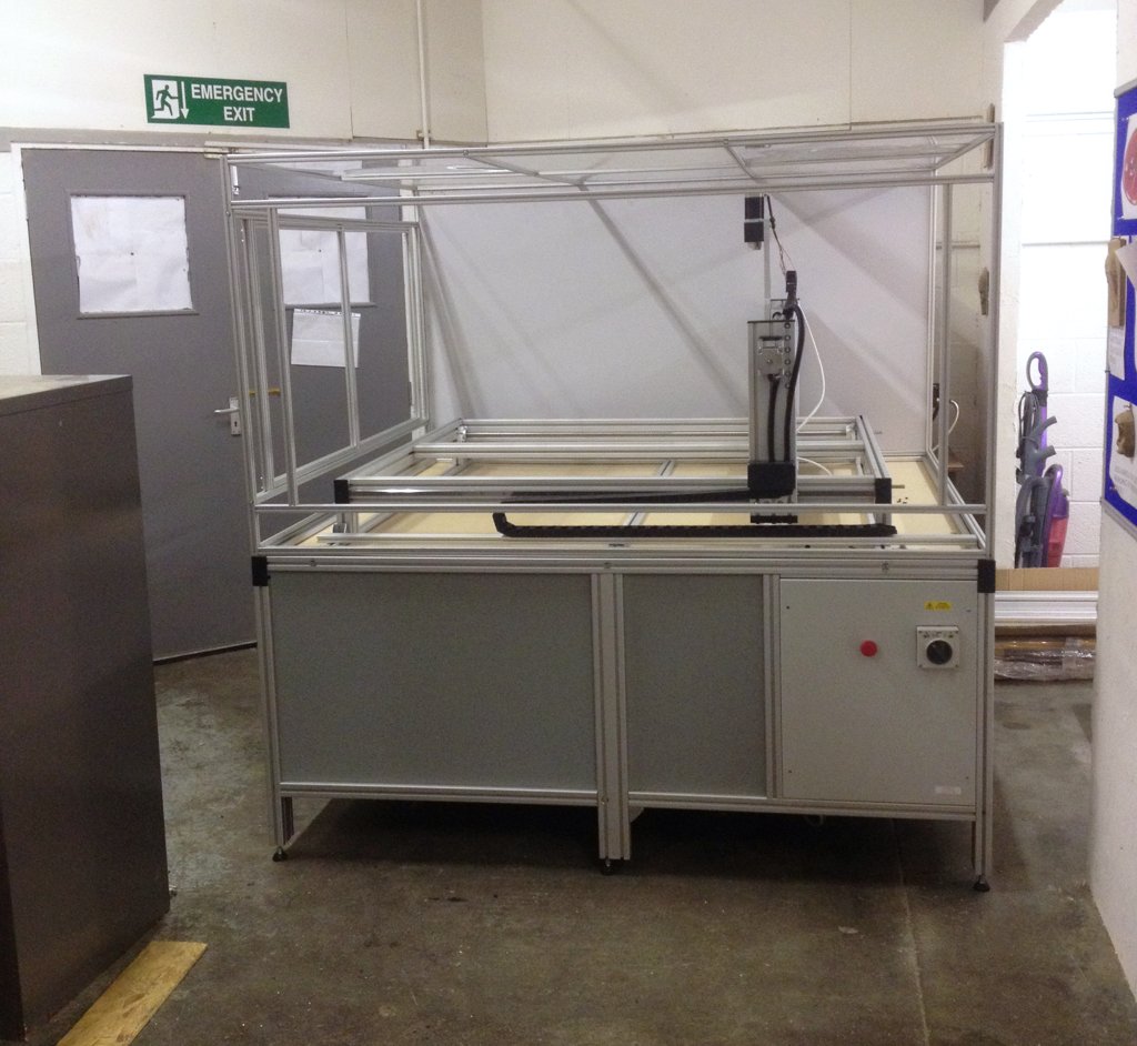
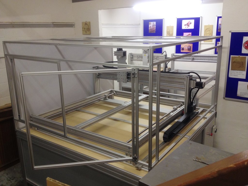
Michael over at Strike sent me a couple of nice images of my work-in-progress machine. The Z axis still needs finishing and lots of small jobs here and there as well as testing but its starting to take shape now. Should be finished within 2 weeks.
I've added on upgraded controllers and dual power supplies in addition to the hiwin rails on the Y axis too.
Getting excited now!
I've added on upgraded controllers and dual power supplies in addition to the hiwin rails on the Y axis too.
Getting excited now!
Attachments

What's the max feed rate and spindle speed? I would think you could feed quite a bit faster than that especially when finishing.
I set 2000mm/min as a conservative figure, at least when starting until I get a feel for what the machine is comfortable with.
The figures I have as absolute maximums (although you'd generally run below these was the impression I got) are as follow:
5000mm/min feed for 10mm DOC with 10mm dia end mill.
7000mm/min feed for finishing
12000mm/min traverse
I'm unsure about spindle speed as all I know is the rpm range; 5000-28000
Spindle speed = rpm range.
I'd definitely try 7000mm/min at some point after you've started to get comfortable with the machine if the manufacturer says it can do it. A real industrial router might cut at 25kmm/min or faster, just for reference. And it might be doing that with a 12mm bit going full depth through 19mm plywood. You can find some fun videos of things like that on youtube.
I'd definitely try 7000mm/min at some point after you've started to get comfortable with the machine if the manufacturer says it can do it. A real industrial router might cut at 25kmm/min or faster, just for reference. And it might be doing that with a 12mm bit going full depth through 19mm plywood. You can find some fun videos of things like that on youtube.
> machine times for the baffle down to approx 7hrs
Ouch. That's why I don't tend to do that sort of milling
Machine looking good. Ah, I see they're using a pair of ball screws down (what I would consider) the X axis. Nice.
Big machine. Big enclosure! Doubt I'd fit that in my garage, sadly.
> 5000mm/min feed for 10mm DOC with 10mm dia end mill.
> 7000mm/min feed for finishing
> 12000mm/min traverse
That does strike (no pun intended) me as very fast for a relatively spindly aluminium machine. My K2 is roughly the same type of build, though smaller so perhaps a little more rigid, and I traverse at only 5000mm/min. I wouldn't dream of trying to do 10mm DOC with a 10mm bit at that speed. I wouldn't do it at 3000mm/min to be honest.
As John's noted, there are huge commercial machines doing very fast speeds with deep cuts, but they're generally running spindles with more HP than my first motorbike)) and made of steel.
Ouch. That's why I don't tend to do that sort of milling
Machine looking good. Ah, I see they're using a pair of ball screws down (what I would consider) the X axis. Nice.
Big machine. Big enclosure! Doubt I'd fit that in my garage, sadly.
> 5000mm/min feed for 10mm DOC with 10mm dia end mill.
> 7000mm/min feed for finishing
> 12000mm/min traverse
That does strike (no pun intended) me as very fast for a relatively spindly aluminium machine. My K2 is roughly the same type of build, though smaller so perhaps a little more rigid, and I traverse at only 5000mm/min. I wouldn't dream of trying to do 10mm DOC with a 10mm bit at that speed. I wouldn't do it at 3000mm/min to be honest.
As John's noted, there are huge commercial machines doing very fast speeds with deep cuts, but they're generally running spindles with more HP than my first motorbike
)) and made of steel.Ouch. That's why I don't tend to do that sort of milling
I'd probably split that up over two to three days. Simply because of all the noise quickly gets annoying. I don't plan on doing those long run times often. For parts like that I'll do a template on the cnc and then make a mold so as to make copies using a pourable mineral filled urethane plastic.
That does strike (no pun intended) me as very fast for a relatively spindly aluminium machine. My K2 is roughly the same type of build, though smaller so perhaps a little more rigid, and I traverse at only 5000mm/min. I wouldn't dream of trying to do 10mm DOC with a 10mm bit at that speed. I wouldn't do it at 3000mm/min to be honest.
Bear in mind that those are maximums and although it wasn't explicitly said I definitely got the impression you'd be wise to run slower than those.
But I do think your probably airing on the side of caution there and your machine is capable of more. Before ordering this one I was demo'd pretty much the same machine but with a smaller, approx 1000 x 600mm, bed doing relatively fast and deep passes in MDF using, if I remember correctly, a 3HP spindle. I don't know the exact speed it was running at nor the DOC but an educated guess tells me it wasn't that far off the numbers he gave. I've seen plenty of utube vids showing 2000mm/min speeds and it was certainly faster than that.
From what I've been told running faster will loose you some accuracy as the machine frame will flex a little and the life expectancy of moving parts will be reduced too. But I do intend to start slow and move up until I find a spot where the machine is comfortable and nothing is going to break before time
I'm in no rush when it comes to cutting but I must admit I was tempted by a couple of used small commercial machines. However I decided as a first machine then buying new(with support and warranty) was more sensible.
Late last year there was one of these on ebay that went for only a little over £6k. Very tempted at that price although later I was glad I didn't because the z travel would have been restrictive.
http://www.trend-uk.com/en/UK/product/CNC_SMARTFAST/3/177/cnc_machining_centre_fast_.html
On a router the base axis is the Y axis - the gantry. The X axis moves across the gantry.
On a router the base axis is what you set it up to be
When I set up my machine, the general advice I was given was that the longest axis is often configured as X. On my machine the travel across the gantry is ~25", and the travel of the gantry along the machine is ~39". As the only space I had for the machine in my garage has me standing with the 39" axis going left/right, that became X.
Obviously with a square machine like Ant's it doesn't really matter. The fact it looks like the access into the enclosure is from the front, then yes, I'd agree that in this instance it would make much more sense for travel across the gantry to be X, and travel of the gantry to be Y.
- Status
- This old topic is closed. If you want to reopen this topic, contact a moderator using the "Report Post" button.
- Home
- Loudspeakers
- Multi-Way
- Apollo Construction Diary