I believe there some confusion here over nomenclature of the modulator output labelling (for which I must take the credit for this confusion).
Would it be correct to say the that first schematic is correct when used with the TI as TI have already inverted the Phase of BP relative to AP to ease the understanding while connecting up the device to the OPS (AP goes to AP on the OPS and likewise BP goes to BP on the OPS). However, from the modulators perspective, in reality the “BP pin” is in fact the modulators “BM” output.
So, if your still with me (I’m not sure if I am ), the second schematic is correct from a true modulators output.
I would agree with Gyula that the inductor values seem wrong, unless you need to double the inductance value of a coupled inductor.
I’m no expert on the subject of inductors, but for a 4Ohm load shouldn’t the inductors be 10uH each, as in an uncoupled inductor design?
But I believe Gyula that your missing the whole point behind the OPS design, which (as understand it) is to gain the advantages of coupled inductors & the carrier cancellation afford by BD modulation (due to the 180Deg Phase shift rather then just the simple phase inversion of AD modulation – so simply using A & B outputs would not offer the full benefits.
As a side note, are you aware that TI has just recently (within the last 2 years) patented the principle behind BD (Tri-State) modulation for their miniature inductor less Class D IC’s? This is really taking the P***, as BD modulation has been known and Patented (Tri-State modulation) for as many years as I can remember. Should they try to enforce the Patent I might ask for this forums help digging up any published documents that describe the principle - before the year 2000. How could the Patent be approved, it seems you can patent (and re-patent) anything you want in the States.
Had a reply back from the Director of Labcenter Electronics (Mr John Jameson) concerning my simulator problems: -
“You seem to have missed the point that the digital models are exactly that - digital parts model in the digital domain behaviour of the components only. We make no claim that they model the analogue behaviour of the parts anything like accurately - that's the whole point of a mixed mode simulator – that the digital models work quickly when used in normal digital circuits.
You'll have all sorts of problems if you try to use them in circuits which depend on their analogue behaviour. You would need to use transistor/mosfet level models for that sort of simulator; we don't bother with that because the whole emphasis in simulation within Proteus is steered towards the VSM / microprocessor stuff.”
Which is a real strange answer, as the simulator has the usual analogue opamps and passive components, AC Analysis, Frequency response, THD and FFT – hardly “emphasis in simulation within Proteus is steered towards the VSM / microprocessor stuff.” And if the “digital models” are just simple models, then why go to all the bother of incorporating the full logic libraries - 74STD, AS, F, HC, HCT, LS, S, ALS, CMOS & ECL, if they are not real devices. If I wanted to do simple digital simulation, I would just use the supplied Laplace & DSIMMDLS (Digital Gates Etc) Libraries, as these surly provide “digital parts model in the digital domain behaviour”
Well as you can guess, I cannot recommend Labcenter’s PROTEUS for mixed simulation work – the fact that even simple functions like the pulse generator, that does not seem to comprehend that a 50% Duty pulse with a Period of 2us and a Rise & Fall time of 1uS each is a Triangle wave, I guess I should know I’m onto a looser. This is a real shame, as I can personally very highly recommend the Proteus PCB and Schematic editors.
Would it be correct to say the that first schematic is correct when used with the TI as TI have already inverted the Phase of BP relative to AP to ease the understanding while connecting up the device to the OPS (AP goes to AP on the OPS and likewise BP goes to BP on the OPS). However, from the modulators perspective, in reality the “BP pin” is in fact the modulators “BM” output.
So, if your still with me (I’m not sure if I am
), the second schematic is correct from a true modulators output.I would agree with Gyula that the inductor values seem wrong, unless you need to double the inductance value of a coupled inductor.
I’m no expert on the subject of inductors, but for a 4Ohm load shouldn’t the inductors be 10uH each, as in an uncoupled inductor design?
But I believe Gyula that your missing the whole point behind the OPS design, which (as understand it) is to gain the advantages of coupled inductors & the carrier cancellation afford by BD modulation (due to the 180Deg Phase shift rather then just the simple phase inversion of AD modulation – so simply using A & B outputs would not offer the full benefits.
As a side note, are you aware that TI has just recently (within the last 2 years) patented the principle behind BD (Tri-State) modulation for their miniature inductor less Class D IC’s? This is really taking the P***, as BD modulation has been known and Patented (Tri-State modulation) for as many years as I can remember. Should they try to enforce the Patent I might ask for this forums help digging up any published documents that describe the principle - before the year 2000. How could the Patent be approved, it seems you can patent (and re-patent) anything you want in the States.
Had a reply back from the Director of Labcenter Electronics (Mr John Jameson) concerning my simulator problems: -
“You seem to have missed the point that the digital models are exactly that - digital parts model in the digital domain behaviour of the components only. We make no claim that they model the analogue behaviour of the parts anything like accurately - that's the whole point of a mixed mode simulator – that the digital models work quickly when used in normal digital circuits.
You'll have all sorts of problems if you try to use them in circuits which depend on their analogue behaviour. You would need to use transistor/mosfet level models for that sort of simulator; we don't bother with that because the whole emphasis in simulation within Proteus is steered towards the VSM / microprocessor stuff.”
Which is a real strange answer, as the simulator has the usual analogue opamps and passive components, AC Analysis, Frequency response, THD and FFT – hardly “emphasis in simulation within Proteus is steered towards the VSM / microprocessor stuff.” And if the “digital models” are just simple models, then why go to all the bother of incorporating the full logic libraries - 74STD, AS, F, HC, HCT, LS, S, ALS, CMOS & ECL, if they are not real devices. If I wanted to do simple digital simulation, I would just use the supplied Laplace & DSIMMDLS (Digital Gates Etc) Libraries, as these surly provide “digital parts model in the digital domain behaviour”
Well as you can guess, I cannot recommend Labcenter’s PROTEUS for mixed simulation work – the fact that even simple functions like the pulse generator, that does not seem to comprehend that a 50% Duty pulse with a Period of 2us and a Rise & Fall time of 1uS each is a Triangle wave, I guess I should know I’m onto a looser. This is a real shame, as I can personally very highly recommend the Proteus PCB and Schematic editors.
Hi Jaka,
Sorry I found your reply to the inductor value – after I posted (V. slow writer)
You mentioned a very important fact. “All materials with distributed gap have non-linear permeability vs. AC and DC flux density and frequency”, unless I’m mistaken, all Toroidal Cores are based upon a “Distributed Gap”. They are in fact mixed with a “Non Conductive, Non Magnetic” filler to achieve this Distributed Gap, and thus preventing a “Shorted Turn”. This would then imply that any inductor based upon a Toroidal core would have worst performance that other cores shapes (Non Distributed Gaps types).
Could you elaborate on your claim / experiences any further?
The ST App. Note AN1013 on Pg 12 talks about Toroid, but only mentions the Hysteresis losses being worst, what is the difference between the Hysteresis curve and permeability vs. AC and DC flux density? As I’ve said earlier – I don’t have any real understanding of inductors / Magnetics.
Would however a Toroid with an air gap still have the linearity issue – once again I’m guessing it would, but I don’t have any practical evidence.
For sure the best Core Material would be plain air – but having to counter the Copper Wire lose issue would result in a very large / expensive component - I heard that Tact use Air Cores.
I still wonder if the “Transformer action” as you rightly call it would reduce the odd-order components I see with the Amidon Toroid inductors. My gut feeling is that it will only help cancel the Even-order components, (Balancing the gain differences on each SIDE of the cycle).
Patent?
Hi John,
to find out, what these abbreviations mean: AD, BD, NADD, NPWM, UPWM and so on, I did some search on it.
Here can you find something:
http://www.icepower.bang-olufsen.com/sw1062.asp
The AES Preprint 4446 explains the modulation schemes and gives some earlier sources at the end of the paper:
http://bogo-united.oeb.tdk.net/graphics/powerhouse/user_graphics/library/aes_publications/4446.pdf
I hope, that is, what you mean.
I believe also, that patent usage switched into the opposite of its prior sense.
Regards, Timo
Hi,
This is what I meant regarding second schematic I posted:
AM = inverted AP
BM = inverted BP
AP and BM have the same duty cycle, but are phase shifted 180 degrees
AM and BP have the same duty cycle, but are phase shifted 180 degrees
Timo, thank you for the links, I was just going to point again to this article with explanation of multiphase BD modulation. Lots of good technical information on that page, but their amplifiers do no sound as well, so they say.
Best regards,
Jaka Racman
inductors
John, all sintered magnetic materials may exhibit an distributed gap, more or less, indpendent of the core format. You have to check the electrical resistance, if you wont't use an extra insulation layer for lower leakage inductance.
And what means linear? One can believe, permeability does not change with flux. It does! So the effective inductance relies on the current and changes with it, slightly upto the hyteresis corner, then abruptlly. It is necessary to check the datasheets of the core material _and_ the core type.
Every material has an different B/H curve, the hysteresis loop may be narrow or wide (hysteretic losses), steep or not (stability of the inductance), sharp or round ("linearity") and so on.
Generally I will use lower flux excursion with growing frequencies. At 100kHz and transformer applications 200mT to 300mT are usual, at 500kHz 100mT or 50mT. Also inductors for resonance or filtering apllication should be used with lower B excursion.
Unfortunately I don't know an good english application handbook, I use an older "EPCOS: Ferrite und Induktivitäten".
Jaka may know a lot about coils.
Regards, Timo
Hello Pitch!
Thank you for the device! I would like to make it from discrete components instead of zxcd1000. I have a very simple schematic for that quartz drived triangle wave generator. It consist of a square wave oscillator which is driving an integrator, but in this way the average value of the output is moving undeterminable. This can be corrected with a high value parallel resistance with the integrator's capacitor, but this point the output is nonlinear. An another method should be used.
This is my problem..
Regards, Gyula
inductor calculations
Hi,
here are some calculations concerning inductive components at around 100kHz from the year 1996. Unfortunately in German, calculations were done in Mathcad 5.0, these files are still available also. I did not check the Math today, so without any guarantee.
If anybody is really interested, I would try to translate them, although I'm a bit lazy.
pushpull
pushpull1
inductor
fourier
Regarding the triangle generator I don't have the right ideas, will keep my eyes open.
Nevertheless I'm positive about the influence of the inductor on the overall distortion and damping factor. The only way to lower its influence is IMO a control (a negative feedback), independent from its analogue or digital design.
The PEDEC idea was interesting for me. The Hypex (originally Philips) and Mueta module measurements show, that similar results can be achieved with a well designed "overall" NFB. This NFB should minimise the residual modulator errors also.
Regards, Timo
Hi Gyula, All,
I know totally zilch about all these digital amps and I can't figure out what's the quartz is doing in the triangle generator.
IMHO, when you define a specific slope for the triangle, and want to switch at specific voltages (for defined avg) without some sort of feedback/servo, then the period of the triangle is already defined and the quartz is out of the job.
If this is OK with you, and you don't need a quartz exact frequency, two comparators, a flip-flop, two ultra high impedance current sources and a cap, will do.
Regards,
Peter Jacobi
Gyula said:I would like to make it from discrete components instead of zxcd1000. I have a very simple schematic for that quartz drived triangle wave generator. It consist of a square wave oscillator which is driving an integrator, but in this way the average value of the output is moving undeterminable. [...]
I know totally zilch about all these digital amps and I can't figure out what's the quartz is doing in the triangle generator.
IMHO, when you define a specific slope for the triangle, and want to switch at specific voltages (for defined avg) without some sort of feedback/servo, then the period of the triangle is already defined and the quartz is out of the job.
If this is OK with you, and you don't need a quartz exact frequency, two comparators, a flip-flop, two ultra high impedance current sources and a cap, will do.
Regards,
Peter Jacobi
Hi Gyula,
Simple FB can be added to the OPAMP integrator you mentioned to restore DC conditions.
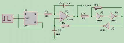
Here’s a basic idea behind the circuit, pls. note I haven’t tested it so you might have to play with the values, Cint depends on the output frequency and amplitude of the Tri Wave required: -
U1 divides the input clock by 2, thereby insuring a 50% duty cycle clock. If the logic is powered from 5V (recommended), the average DC voltage of the Clock will be 2V5. The output from U1 is fed into the Integrator by R1 (keep it value below 1K to prevent noise, adjust C2 - Cint) the integrator generates the Triangle wave (insure the Opamp is unity gain stable – due to the 100% FB though C2). The output is “sliced” at about 2.5V by the “Comparator” based on U3 & U4 with R2 & R3 creating a small amount of hysteresis (this hysteresis will cause a very small offset error). U5, C1, R4 filter the resultant square wave from the output of the comparator - who’s duty depends on the DC offset at output of the OPAMP. The Opamp then insures the average DC voltage on its Non Inverting and Inverting inputs (2.5V) are the same.
I hope it's helpful, John
Simple FB can be added to the OPAMP integrator you mentioned to restore DC conditions.
Here’s a basic idea behind the circuit, pls. note I haven’t tested it so you might have to play with the values, Cint depends on the output frequency and amplitude of the Tri Wave required: -
U1 divides the input clock by 2, thereby insuring a 50% duty cycle clock. If the logic is powered from 5V (recommended), the average DC voltage of the Clock will be 2V5. The output from U1 is fed into the Integrator by R1 (keep it value below 1K to prevent noise, adjust C2 - Cint) the integrator generates the Triangle wave (insure the Opamp is unity gain stable – due to the 100% FB though C2). The output is “sliced” at about 2.5V by the “Comparator” based on U3 & U4 with R2 & R3 creating a small amount of hysteresis (this hysteresis will cause a very small offset error). U5, C1, R4 filter the resultant square wave from the output of the comparator - who’s duty depends on the DC offset at output of the OPAMP. The Opamp then insures the average DC voltage on its Non Inverting and Inverting inputs (2.5V) are the same.
I hope it's helpful, John
Attachments
triangle
Hi Gyula,
may this idea work for your triangle shaper? I did not prove it, only simulated.
The trick is, to connect the feedback resistor R38 before the integrating resistor R37, not across the integrating capacitor, C35.
All component values have to be changed regarding your design.
For DC and therefore the AC arithmetic average value the network R39, C37, R38 should act as a short between U6A's output and his noninverting input - creating a voltage follower. R38 should possibly get a larger value, depending on the stabilisation time and the input bias current of the OPA.
Good Luck!
Attachments
triangel
Here is the simulated stabilisation behaviour.
red - input 1MHz rectangle 1V (plus 16kHz 10mV sine, as disturbation)
blue - voltage at the inverting input of the OPA
yellow - output
Wow, the other guys were really fast, but my 'solution' looks simpler!
Regards, Timo
Here is the simulated stabilisation behaviour.
red - input 1MHz rectangle 1V (plus 16kHz 10mV sine, as disturbation)
blue - voltage at the inverting input of the OPA
yellow - output
Wow, the other guys were really fast, but my 'solution' looks simpler!
Regards, Timo
Attachments
Hi John, Timo, Jaka and Peter!
Peter, I'm understanding your doubts, I just thought it before written the question. The quartz control is needed for eliminate the thermal dependence.
John and Timo, thank you for the really fast help and the simulation ! It will be a big help for me to do an analog modulator.
Jaka, I did your suggested modification for class-I. You suggested that the mosfets' discharging should be delayed to avoid the coils' exhaustion. The result is quite GOOD!
Jaka, thank you for your help!!
The drowning is just a little amount in the sound already, a little bit more delay still should be done.. I think the high range of the sound is really better even in this case, than it was in class-D. There are two paralleled SGS Th. IRF540 in the output stage's upper and lower sides, driven with the IR2110 through a (47 microhenry) x (MBR1100 Schottky) with cathode to the fets. When the fets were connected directly to the driver's output, the drowning was horrible, I didn't think the histeresis, Rds/on/, and Uf losses is such a great amount.
The coils were made from two A-324117-2 Arnold MPP toroids with 16 turns on each of them. A little bit small ones, but in my country only this type of Arnold MPP was obtainable (for approximately 2 weeks), so the situation in this country is drastic.. really.
I don't understand what crown writes at his homepage (with illustrations) : class-I recirculates the reactive energy (current from the speakers' inductance), and the other topologies don't.
It almost have done with class-D. what a blame!
I'm just listening to the amp. with 15V supply (there wasn't supply connected to the outputs when I wrote the first lines, so I probed it just with the energy carried by the millers to the puffers.
Now it's really great!! The drowning is nearly disappeared at 15 V. Already, this amp. is also better than Quad 405. I will try it from 96 V tomorrow.. There isn't current limiting in the PSU, so it will be thrilling.
The attached file is a short class-I guide from Crown.
Thank you for your help again!
Regards,
Gyula
Peter, I'm understanding your doubts, I just thought it before written the question. The quartz control is needed for eliminate the thermal dependence.
John and Timo, thank you for the really fast help and the simulation
! It will be a big help for me to do an analog modulator.Jaka, I did your suggested modification for class-I. You suggested that the mosfets' discharging should be delayed to avoid the coils' exhaustion. The result is quite GOOD!
Jaka, thank you for your help!!
The drowning is just a little amount in the sound already, a little bit more delay still should be done.. I think the high range of the sound is really better even in this case, than it was in class-D. There are two paralleled SGS Th. IRF540 in the output stage's upper and lower sides, driven with the IR2110 through a (47 microhenry) x (MBR1100 Schottky) with cathode to the fets. When the fets were connected directly to the driver's output, the drowning was horrible, I didn't think the histeresis, Rds/on/, and Uf losses is such a great amount.
The coils were made from two A-324117-2 Arnold MPP toroids with 16 turns on each of them. A little bit small ones, but in my country only this type of Arnold MPP was obtainable (for approximately 2 weeks), so the situation in this country is drastic.. really.
I don't understand what crown writes at his homepage (with illustrations) : class-I recirculates the reactive energy (current from the speakers' inductance), and the other topologies don't.
It almost have done with class-D. what a blame!
I'm just listening to the amp. with 15V supply (there wasn't supply connected to the outputs when I wrote the first lines, so I probed it just with the energy carried by the millers to the puffers.
Now it's really great!! The drowning is nearly disappeared at 15 V. Already, this amp. is also better than Quad 405.
I will try it from 96 V tomorrow.. There isn't current limiting in the PSU, so it will be thrilling. The attached file is a short class-I guide from Crown.
Thank you for your help again!
Regards,
Gyula
Hi,
Class-I is working. Such sounds come from the speakers like I never heard in the music before. The sound is crystal clear. Class-I is really better because of the nonexistent deadtime. But the circuit failed at 96V. I added a serial 230V 100W bulb between the PSU and the output stage. The bulb did approximately 260 mA current limiting, it was causing the supply voltage of the output was limited to 23V. Then I did a mistake: I reseted the receiver, so the valid outputs of the TAS gone to low state and the output switched to high-Z state through the IR2110's SD pin. The supply voltage rose to 96V and I have released the receiver's reset, the output has broken down. The lower side's clamper and the driver's high side were damaged. I haven't got another IR2110 at home.
I think Crown's output stage has got a current sensing and in this way that's capable to set the repose duty factor. This is easier in analog.
Peter, I think you block diagram is good. The SRCs' inputs must be the slave and the outputs must be the master.
Good luck,
Gyula
Class-I is working. Such sounds come from the speakers like I never heard in the music before. The sound is crystal clear. Class-I is really better because of the nonexistent deadtime. But the circuit failed at 96V. I added a serial 230V 100W bulb between the PSU and the output stage. The bulb did approximately 260 mA current limiting, it was causing the supply voltage of the output was limited to 23V.
Then I did a mistake: I reseted the receiver, so the valid outputs of the TAS gone to low state and the output switched to high-Z state through the IR2110's SD pin. The supply voltage rose to 96V and I have released the receiver's reset, the output has broken down. The lower side's clamper and the driver's high side were damaged. I haven't got another IR2110 at home.I think Crown's output stage has got a current sensing and in this way that's capable to set the repose duty factor. This is easier in analog.
Peter, I think you block diagram is good. The SRCs' inputs must be the slave and the outputs must be the master.
Good luck,
Gyula
Hi Gyula,
I am glad that you succeded with your amplifier. Could you tell me what was the added delay?
Here are some pages I scanned from an old (1988) article. Described is crystal driven triangle modulator and also output filter with notch stage. (John might be interested).
John,
for you there is a Magnetics Design Handbook . It explains why distributed gap cores have inherently nonlinear B-H characteristic and how you linearize nonlinear ferrite with discrete gap. Another point might be Zetex ZXCD1000. In an older version of the datasheet they were claiming that they need special magnetics to achieve low distortion. Well this is their special magnetics.
For teaser, attached is a picture of 25kHz output from class D amplifier running open loop. It is from the article i scanned.
Best regards,
Jaka Racman
Attachments
Hi Jaka,
Thanks for the Inductor Link – its been extremely useful. The link goes into great detail concerning the rounding of the B-H characteristics – which I now stongly believe to be the main cause of the Odd-Order distortion I’m finding with Toroidal Cores.
I have a problem distinguishing between the core material types i.e. the article in the Link talks about Metal-Alloy cores (Good Square loop) & Composite Powered Metal cores (Poor soft loop) but then core manufactures talk about Iron Power cores… but at least I have a better understand of what I’m looking for – ALWAYS a great help in life!
Yes, one of the Grandfathers of Class D, Brain Attwood designed the ZXCW1000, which is not a bad device for its target market - but it doesn’t make the grade for Hi-Fi amp. However, that said it does sound better then Tri-Paths Class T.
Thanks for scanning the Class D Info - maybe I’m slow, but it’s not immediately obvious to me which components in the LPF comprise the Notch Filter?
There’s some good information in the equivalent circuit for the output filter - better models for the Caps Etc. Guess I will have to load it into my Simulator to find how the Notch is created.
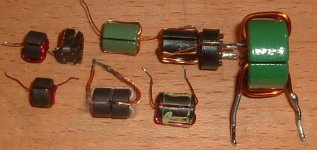
Here’s a picture of some of the many inductors that where tried for the Zetex inductor solution – I hope that Pulse are not trying to take the credit for the inductor design! – Which are good for there target market @ 0.013% @ 100W Open Loop (for the big green ones) – but are nowhere near my target of less then 0.00005%!
Thanks for the Inductor Link – its been extremely useful. The link goes into great detail concerning the rounding of the B-H characteristics – which I now stongly believe to be the main cause of the Odd-Order distortion I’m finding with Toroidal Cores.
I have a problem distinguishing between the core material types i.e. the article in the Link talks about Metal-Alloy cores (Good Square loop) & Composite Powered Metal cores (Poor soft loop) but then core manufactures talk about Iron Power cores… but at least I have a better understand of what I’m looking for – ALWAYS a great help in life!
Yes, one of the Grandfathers of Class D, Brain Attwood designed the ZXCW1000, which is not a bad device for its target market - but it doesn’t make the grade for Hi-Fi amp. However, that said it does sound better then Tri-Paths Class T.
Thanks for scanning the Class D Info - maybe I’m slow, but it’s not immediately obvious to me which components in the LPF comprise the Notch Filter?
There’s some good information in the equivalent circuit for the output filter - better models for the Caps Etc. Guess I will have to load it into my Simulator to find how the Notch is created.
Here’s a picture of some of the many inductors that where tried for the Zetex inductor solution – I hope that Pulse are not trying to take the credit for the inductor design! – Which are good for there target market @ 0.013% @ 100W Open Loop (for the big green ones) – but are nowhere near my target of less then 0.00005%!
Attachments
Hi Jaka,
I attached the original "digitalis" circuit in .doc format. For class-I, I turned over the MBRs at the fets' Gates. So, they are accelerating the charging of the fets, and the inductors delaying and slowing down the discharging of the fets. This solution was useful at 15V supply. Thanks for the great scan!
Regards,
Gyula
Attachments
- Status
- This old topic is closed. If you want to reopen this topic, contact a moderator using the "Report Post" button.
- Home
- Amplifiers
- Class D
- Anyone interested in a digital amplifier project?