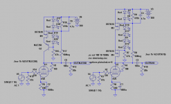
These are the circuits.
The recommended BJT has a tad higher THD but more important, it has LOWER 3rd and uneven harmonics.
.SUBCKT 6V6 P S G K
Esp 2 0 VALUE={V(P,K)+13.49*V(S,K)+130.4*V(G,K)}
E1 3 2 VALUE={5.521E-7*(PWR(V(2),1.5)+PWRS(V(2),1.5))/2}
E2 3 4 VALUE={5.521E-7*PWR(13.49*V(S,K),1.5)*V(P,K)/25}
E3 5 4 VALUE={(1-V(4,2)/ABS(V(4,2)+0.001))/2}
R1 5 0 1.0K
Gk S K VALUE={V(3,2)}
Gp P S VALUE={0.92*(V(3,4)*(1-V(5,4))+V(3,2)*V(5,4))}
Cgk G K 4.5P
Cgs G S 4.5P
Cgp G P 0.7P
Cpk P K 7.5P
.ENDS 6V6
Attachments
") .
.SY said:
Longer tube life? Do you mean because of the inability of the bias voltage to adjust itself as the tube ages and starts getting gassier?
Yes, I mean that negative feedback on DC that we loose stabilizing an absolute value of a bias voltage.
I missed this thread before, sorry. Otherwise I would have commented on your very clever circuit. That's an interesting variation on a CCS. I use gyrators for active crossovers, but never have as a plate load. Excellent idea!
Thanks! It was a logical evolution of this servo (a first, I decided to load the tube on a CCS, and then decided to shorten the servo path so it's impact on the signal will be less audible):
As I mentioned earlier you must use the Ua/Ia-curves to decide workingpoint.
With 6V6-trioded, B+ 300V , Ia 20mA, load above 10k and the BJT/Mosfet version, we can swing between 65-70V and 290V. This means the workingpoint should be choosen at ca 180V. This is where you will get symmetric clipping and max output.
With 6V6-trioded, B+ 300V , Ia 20mA, load above 10k and the BJT/Mosfet version, we can swing between 65-70V and 290V. This means the workingpoint should be choosen at ca 180V. This is where you will get symmetric clipping and max output.
For valves with a lot of voltage swing, such as your examples, I guess you would need to drop quite a bit of B+ across the transistors, but what about a preamp with only a few volts swing?
In post 55, Revintage quotes an equivalence to about a 60H choke. One of the great advantages of loading an anode with inductance is that it allows you to run off a lower B+ while still maintaining your voltage swing. Does this not also apply with this circuit?
In post 55, Revintage quotes an equivalence to about a 60H choke. One of the great advantages of loading an anode with inductance is that it allows you to run off a lower B+ while still maintaining your voltage swing. Does this not also apply with this circuit?
hihopes said:
In post 55, Revintage quotes an equivalence to about a 60H choke. One of the great advantages of loading an anode with inductance is that it allows you to run off a lower B+ while still maintaining your voltage swing. Does this not also apply with this circuit?
No, it is not a real coil that saves an energy in a magnetic field, it is an electronic simulation of a coil that spends an extra energy to work. But it dissipates much less of an energy than a plain resistor would do for the same results.
I have downloaded the datasheet for irf9610 from International Rectifier, but it doesn't show the pinout - just says it is a TO220AB package. As far as I can find out, this seems to have a pinout of G,D,S (looking from the front). Can anyone confirm this? I am drawing up a PCB and obviously need to get this right. I can post a jpg of the PCB if anyone is interested, or would like to give feedback on it.
- Status
- This old topic is closed. If you want to reopen this topic, contact a moderator using the "Report Post" button.
- Home
- Amplifiers
- Tubes / Valves
- Anti-Triode SEPP, how to do best?