Wavebourn said:Hmmm.... I'm afraid you will need too many LEDs. Like a Green Light District (GLD, SY?)
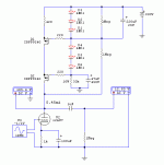
Here it is Wavebourn. This is what I think I can do with recycling my post#2 CCS (the green LEDs one on the post#17 pic).
Does this count for a cascoded Mosfet gyrator (electronic choke)? Did I get it right at all?
I have included a 12AU7 common cathode simulation so to see how it reacts. The 420R resistor on top of the first Mosfet sets the current. It can be a 500R trimmer for using other tubes, namely my 6V6 trioded or a 12B4A in another preamp that I wanna test the gyrator too. The 33K 10W feeds 10mA so the LEDs can work low noise, and its Johnson noise is filtered by the 47uF not to reach the cascode's gate.
Attachments
Michael Koster said:It doesn't matter really how you
develop the fixed voltage. It can be used with fixed bias because it
can regulate the plate voltage.
Cheers,
Michael
Can I get the fixed voltage from a divider on B+ ? How higher than the anode voltage it must roughly be?
So what happens when you filter the best ideas of
Michael J Koster, Wavebourn, and Nelson Pass
through the strange mind of Ken? Heck if I know...
Pretend Zen is a Triode, same thing only sandy.
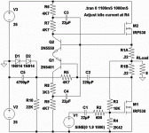
Only trying to show you the active source servo.
I'll bend it around a real triode here soon enough.
Good Ash? Bad Ash? I'm the one with the Aleph.
******* evil mirrored clones, what can you do?
Attachments
So in theory:
At DC: its a Voltage source
At some subsonic frequency:
Its a gyrator of aproximately
equal and constant current.
Above 20Hz: Its Anti-Triode
or Aleph or whatever...
---------------
And LTSpice seems to agree.
---------------
Just needs a sourceOdyne
to flip a ground level input
common to the bottom rail.
You might notice the oddball 3K3 in the lower Bootstrap.
Why? Cause currents in R7 and R8 tend to be the same.
With a Symmetrical 4K7, bootstrapping wasn't happening
at all for the lower end. Indeed, the collector lost a volt
or two somewhere.
Tweaking it to 3K3 gave it the same -30V peak as the
upper collector's +30V Peak. Problem solved...
Why? Cause currents in R7 and R8 tend to be the same.
With a Symmetrical 4K7, bootstrapping wasn't happening
at all for the lower end. Indeed, the collector lost a volt
or two somewhere.
Tweaking it to 3K3 gave it the same -30V peak as the
upper collector's +30V Peak. Problem solved...
salas said:
Here it is Wavebourn. This is what I think I can do with recycling my post#2 CCS (the green LEDs one on the post#17 pic).
Does this count for a cascoded Mosfet gyrator (electronic choke)? Did I get it right at all?
I have included a 12AU7 common cathode simulation so to see how it reacts. The 420R resistor on top of the first Mosfet sets the current. It can be a 500R trimmer for using other tubes, namely my 6V6 trioded or a 12B4A in another preamp that I wanna test the gyrator too. The 33K 10W feeds 10mA so the LEDs can work low noise, and its Johnson noise is filtered by the 47uF not to reach the cascode's gate.
1. 47 uF in series with LEDs is odd. Instead of decreasing voltage variations it increases them. Remove it.
2. 220 uF in servo feedback is too high for 1 mOhm resistor. Recauculate it for a reasonable time constant.
3. Voltage divider in servo feedback is formed by equal 1MOhm resistors. You have to increase the value of a bottom one many times, or decrease a value of the upper one to set proper anode voltage. If you need voltage drop on the upper resistor about 3V, on lower resistor about 150V, what should be their values?
Start from selecting the value of the bottom one, like 10 MOhm. Actually, 1 MOhm will be high enough comparing with Rp of your tube, so 150/3=50, i.e. the upper one should have 50 times smaller value, i.e. in case of lower one 1 mOhm it should be 20 KOhm. Use 50K trimmer to set it properly. Then select the capacitance, say for 1 Hz corner with 20 KOhm resistor.
And the last, a mistake in your drawing: you connected servo feedback to LEDs. Disconnect it. Gate of the upper FET should go to the servo feedback divider.
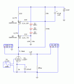
salas said:Problem is, how do I keep the upper Mosfet on, If I don't put LEDs on its gate? I guess with the upper divider Vdrop?
It is the main point of my idea that Kenpeter described, "That is absurdly cool!"
Upper MOSFET generates current needed to keep a constant voltage on the plate!
I would add 3 more LEDs in series. You have plenty of voltage available, use it.
Also, I would remove that 600 Ohm resistor: it is not needed here (it was needed for your version of CCS with stable gate voltage), increasing that 330K about twice. Better, as I said, use 1M resistor and 50K trimmer for breadboarding. Also, 47 uF is too high value: I would decrease it to say 2 uF using a metal film cap.
And, finally, I would consider different transistors (smaller capacitances for better frequency response) since you need about 5 mA only.
I did not use all my LEDs available (6) on that because it was distorting the sinewave on upper Mosfet's source when the 600R was present and all LEDs employed. I was using it to trim the current, but if the upper divider will be a trimmer, its not needed as you say.
So, given what I got on the perfboards, do you think that this one will make do? (Thanks for your assistance, each time you tell me to change something I grasp your idea's mechanism better). I will use film cap, no problem, the 47uF there is just random. For the moment IRFPs I got on the boards. The 12AU7 is indicative. I will use 15-20mA and 6V6 trioded or 12B4A. Can you tell me what to expect sonically versus a typical CCS?
So, given what I got on the perfboards, do you think that this one will make do? (Thanks for your assistance, each time you tell me to change something I grasp your idea's mechanism better). I will use film cap, no problem, the 47uF there is just random. For the moment IRFPs I got on the boards. The 12AU7 is indicative. I will use 15-20mA and 6V6 trioded or 12B4A. Can you tell me what to expect sonically versus a typical CCS?
Attachments
salas said:I did not use all my LEDs available (6) on that because it was distorting the sinewave on upper Mosfet's source when the 600R was present and all LEDs employed. I was using it to trim the current, but if the upper divider will be a trimmer, its not needed as you say.
So, given what I got on the perfboards, do you think that this one will make do? (Thanks for your assistance, each time you tell me to change something I grasp your idea's mechanism better).
Looks Ok, excepr 47 uF cap. Do you have some metal film, about 2.2 uF or 4.7 uF?
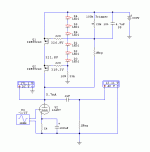
Less added hiss I hope too. Because the typical CCSs pushed them tubes to hiss a little more or much more compared to resistive loading at same bias points. Also look at the edited schematic, I added a trimmer and changed 47uF to 4,7uF PP. The 100k trimmer I hope gives me enough range so to climb up to 20mA with other tubes.
P.S. The added hiss was messing with sibilance. It was like going from a Manley mic pre to a Behringer. The other ranges remained cleaner and dynamic with typical CCS, but more mechanical than with Rload.
EDIT: The depletion constant voltage anti-triode cascode that M.Koster has shown is yummy too. Soldering iron time. First yours, looks very good and the now CCS boards are compatible.
EDIT: The depletion constant voltage anti-triode cascode that M.Koster has shown is yummy too. Soldering iron time. First yours, looks very good and the now CCS boards are compatible.

I would not expect less of hiss from better self-balance. I hear several reasons of added hiss: hiss added by odd charge carriers in semiconductors (transistors, LEDs), and higher amplification factor of tube's own noises because of higher dynamic resistance of anode load.
salas said:The Mu gets pushed, OK. But my experience is that I got reasonably more hiss with Mosfet cascode, but too much with BJT CCS for exactly the same bias points. But gyrator is constant voltage, so it must not impose any strict current condition, I suppose.
On AC it is a constant current source. Servo feedback may decrease level of rumble, but not of hiss.
- Status
- This old topic is closed. If you want to reopen this topic, contact a moderator using the "Report Post" button.
- Home
- Amplifiers
- Tubes / Valves
- Anti-Triode SEPP, how to do best?


