At this point, I'm 100% sure Wavebourn's solution is far more
relevant to Silas' immediate needs. But I'm gonna post this
anyway. Worked too darn hard on it not to.
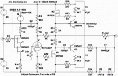
Zen bent backwards through a real triode controls the mess.
Aleph with the gyrator thingie goin on is the Anti-Triode.
The JFET cascode up front moves the signal common to the
bottom rail, and improves overall PSRR. No voltage gain here.
Center holds plenty well enough to be both OTL and OCL.
Only thing I don't care for is 1000uf coupling cap, but was
necessary evil to swing Zen and Aleph in phase at 20Hz.
I'll be thinking hard how to get rid of it.
Attachments
So: D1 + D2 creates the -1.25V servo reference.
Emitters of Q1 + Q2 simply stand on top of that,
And .44V dropped thru R5 when set to idle at 2A.
We are back at GND without too much error.
Q1 and Q2 serve completely different functions,
though I've drawn them sort of symetrical, as
they both need a similar bootstrapping.
The source of the upper mosfet was chosen to
drive both bootstraps, cause it has the lowest
impedance, and least effect upon the output.
The 3K3 in the lower bootstrap is no mistake.
If its the same as the top side, it don't work.
Both straps grant an extra +/-5V to drive with.
kenpeter said:
The 3K3 in the lower bootstrap is no mistake.
If its the same as the top side, it don't work.
Do you need it at all?
Wavebourn said:Do you need it at all?
Only if swinging 35W SE triode within 1V of either rail.
Actually, in this case, its more like SE UL...
I had problems with grid leak when starving the plate
too much in saturation. And VGS bias when too near
cutoff. So the triode couldn't easily be run full swing.
But that doesn't mean I was ready to abandon it.
I've cheated and abused its plate to become in effect
the "screen" of the lower mosfet. 50% feedback etc...
Triode stays at happy (though awfully low) voltages.
Wavebourn said:Edit: it is a source follower loaded on a counter - modulated CCS.
OK, now I get it. The counter modulated
part of it anyways...
Shouldn't the triode drive a small but fair
portion of the real load, rather than looking
into an inverted copy?
salas said:

Are you gonna build this?
Probably two. With Eminence Wizards.
In Karlson Klam front loaded cabinets.
The slanted baffles left open in back
to fake very short horns.
kenpeter said:
OK, now I get it. The counter modulated
part of it anyways...
Yes, but feed-forward counter-modulated!
Shouldn't the triode drive a small but fair
portion of the real load, rather than looking
into an inverted copy?
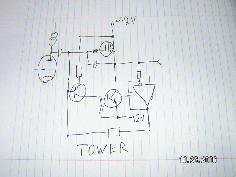
Here is the real thing I made then, it is different triode loadwise:

Looks Ok, excepr 47 uF cap. Do you have some metal film, about 2.2 uF or 4.7 uF?
Wavebourn,
Checked Salas circuit in LTspice and lowend gets f-cked up when going down this low. 4,7u gives a Fu of 95Hz. So to reach down to 5Hz the cap has to be 100u!
I also get a peak of +6dB at 150kHz.
Otherwise it sims fine when using proper tubes instead of 12AU7.
Compared to a 100H choke the PSRR is almost on par, but compared to a CCS it is lousy.
I wouldn't sweat LTSpice. Gives goofy answers that might be
frequency dependent anytime the impedances swing too stiffly.
I like to set up a dummy signal at 96KHz just to make sure it
don't attempt too many "smart" calculation shortcuts. Quite
a significant calming effect upon the higher order harmonics.
frequency dependent anytime the impedances swing too stiffly.
I like to set up a dummy signal at 96KHz just to make sure it
don't attempt too many "smart" calculation shortcuts. Quite
a significant calming effect upon the higher order harmonics.
Kenpeter,
So, what does your sims say?
I didn´t care very much about the peak as it might as well be the MOSFET-models. Checked with some other models and it was gone.
But the hf-peak wasn´t the issue, it was the calculation of the 47uF cap with its -3dB at 95Hz. Also a possible bettering of PSRR could be of interest.
In simple terms:
Seems like the gyrator as is about equivalent to a ca 60H/2k choke with a parallell cap of ca 60p. But without the low-end loss of it.
It also seems to have the equivalent resistance of over 300k.
Nice circuit!
revintage said:
Wavebourn,
Checked Salas circuit in LTspice and lowend gets f-cked up when going down this low. 4,7u gives a Fu of 95Hz. So to reach down to 5Hz the cap has to be 100u!
I also get a peak of +6dB at 150kHz.
Otherwise it sims fine when using proper tubes instead of 12AU7.
Compared to a 100H choke the PSRR is almost on par, but compared to a CCS it is lousy.
1'st order network with a peak? Did you sim something else instead of what was drawn?
With PSRR in mind it should be referenced to the ground, i.e. different topology, but the same idea.
Mine? Not currently relevant to Anti-Triode, though could be...revintage said:Kenpeter,
So, what does your sims say?
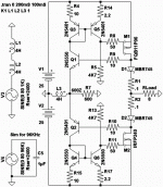
All harmonics in this example FFT -85db down or better...
Couldn't best -45db without the 96KHz dummy circuit you
might take notice in the lower left corner.
Try this same LTSpice trick with Wavebourn's Gyrator, may
give better simulated results.
Attachments
revintage said:Wavebourn,
Read my two posts again. It was not about the hf-peak!
It was about the lowend, with the 4.7u you recommended one get -3dB at 95Hz! Did you sim or calculate the value at all?
About the cap to ground, sim it! Didn´t work for me.
I simmed and calculated in mind, fot 6V6 tube. Sorry. Use 47 uF, or 4.7 uF, but ten times higher values of resistors.
Speaking of reference to ground, it is not the cap to ground; it is a voltage regulation in respect to ground. Different topology. But instead of that I would prefer better PS filtering.
- Status
- This old topic is closed. If you want to reopen this topic, contact a moderator using the "Report Post" button.
- Home
- Amplifiers
- Tubes / Valves
- Anti-Triode SEPP, how to do best?


