kenpeter said:I ran into a dude this weekend who wants to drive electrostatic
speakers with 845's . I suggested he find this thread and consider
gyrators for his plate loads, rather than his originally planned 8K
resistors. That both front and back of his statics might idle exactly
660V, with no special worries for DC matching...
However, his B+ is likely to be 1100V. So some rethink may be in
order how to keep such gyrators from blowing up. Are any P-type
devices able to handle it? How might one do this with N-Channel
IGBT's? And rather than simply gyrate, I'd like to investigate if its
also possible to have anti- triode behavior above DC.
The gyrator circuit as I understand will source current into the load
up to the quiescent current. Can it source more than that?
A series push-pull anti-triode as I understand it can approach 2X
the quiescent current into the load, which is the quiescent current plus
the mirrored inverse signal flowing through the triode. I.e. if the
triode current goes to zero, the current sourced into the load will be
2 * Iq by the anti-triode.
Another way of thinking about this is that the anti-triode and the
triode each share 1/2 the load, resulting in the triode seeing 2X
the load impedance vs. a choke or gyrator, assuming the same OPT
primary impedance.
What does this mean? For a given tube and OP, the primary impedance
can be reduced by 1/2 compared to a gyrator, resulting in 2X
power output. Or the Zo can be reduced. Or both. The anti-triode
allows the amp to use the power dissipated in the active load to
power the output.
Ken, I think direct drive of ESLs may be a sweet application of this
series push-pull anti-triode circuit. The B+ and the max Vds/Vce will
need to be about 2X the quiescent Va or maybe a little less. The
reduction in Zo by 1/2 will be useful.
Here's what I'm working on for 4-65As, Vak of about 650V, B+
about 1200V, Zo with 4-65As (845 also) will be about 800 ohms.
I'm expecting about 40W into a 4K load, parafeed into an OPT.
Two of these in an H-bridge could provide up to 80 Watts, which
should be a nice power level for ESLs.
I haven't looked at the actual load impedance presented by the
ESL though, to see what the Po and DF would end up being.
Cheers,
Michael
Attachments
hihopes said:"I can add a voltage regulator on top."
Won't that be much more complex (and expensive)?
Sure. But PSRR of the gyrator (on audible frequencies) is the same as PSRR of the current source of similar complexity. If you want more PSRR on frequencies below than a current source provides I can add an active filter or even a voltage regulator on top.
About MOSFETs, why not use 2SJ79 that has much lower capacitance than 9610.
Wavebourn,
Mentioned this earlier in this thread, but my sims show that PSRR is on par with a choke but not as good as a two transistor CCS.
Will do some more sims to verify.
kenpeter and MJK,
The solutions you talk of are constant current and exatctly as the name of the thread says. But the name is misleading as it has ended up with Wavebourns elegant solution that is constant voltage not current. This should be very useful when DC-coupling to a next stage(thinking of a two-stage SE).
Trim the resistor that is in parallell with the cap to set voltage.
Trim the cathode resistor(or bias voltage) to set current.
Trim the cap to set inductance.
As close as you can get to iron, with the help of sand") !
!
But PSRR of the gyrator (on audible frequencies) is the same as PSRR of the current source of similar complexity.
Wavebourn,
Mentioned this earlier in this thread, but my sims show that PSRR is on par with a choke but not as good as a two transistor CCS.
Will do some more sims to verify.
kenpeter and MJK,
The solutions you talk of are constant current and exatctly as the name of the thread says. But the name is misleading as it has ended up with Wavebourns elegant solution that is constant voltage not current. This should be very useful when DC-coupling to a next stage(thinking of a two-stage SE).
Trim the resistor that is in parallell with the cap to set voltage.
Trim the cathode resistor(or bias voltage) to set current.
Trim the cap to set inductance.
As close as you can get to iron, with the help of sand
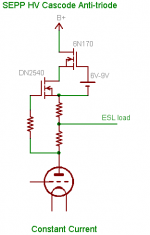
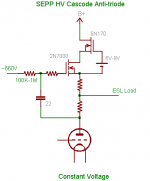
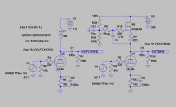
!kenpeter said:Yeah, AC like what Michael was saying. But DC to center on 660V
no matter how the tube(s) age. Just like Wavebourn's Gyrator.
Just need a slick way to do both in one circuit what don't splodie.
This should do the trick. Constant anode voltage, no matter
what. Still sources up to 2X Iq and reduces Zo by 2X as in
the constant Iq version.
This circuit is also very nice as a fixed bias driver.
Lars, here's a low capacitance MOSFET - 2N7000 -
but it's bootstrapped by the source resistor anyway.
Michael
Attachments
revintage said:kenpeter and MJK,
The solutions you talk of are constant current and exatctly as the name of the thread says. But the name is misleading as it has ended up with Wavebourns elegant solution that is constant voltage not current. This should be very useful when DC-coupling to a next stage(thinking of a two-stage SE).
I understand the value of both circuits and the differences.
I believe Michael's post above proves the point I was trying
to make. These two behaviors are not mutually exclusive.
As for P-Channel? In Wavebourn's circuit, just stick with bipolar.
But more to answer your real question, you can expand upon your
P-channel choices to include enhancement mode. A floating battery
bias will last a long time in an application with no DC gate current.
Or Nelson Pass's Aleph is another way to fake an enhancement
MOSFET to act like a depletion type with -0.66V or any string of
diodes turn on voltage.
In Michael's circuit above, no P- types are needed. It also seems
to matter very little the MOSFETs are enhancement or depletion
types. Either will work. IGBT is an option here too.
revintage said:Hi Michael,
The 60V 2N7000 is N-channel and will not work in Wavebourns circuit. Any P-channel suggestions?
How about the Vishay TP0610K? I'm looking at this one for use as the
constant voltage device in a cascode active-loaded "ultra" cathode
follower:
http://www.datasheetcatalog.org/datasheet/vishay/71411.pdf
Attachments
Michael Koster said:
This should do the trick. Constant anode voltage, no matter
what. Still sources up to 2X Iq and reduces Zo by 2X as in
the constant Iq version.
This circuit is also very nice as a fixed bias driver.
Lars, here's a low capacitance MOSFET - 2N7000 -
but it's bootstrapped by the source resistor anyway.
Michael
Looks really nice!
A string of LEDS and one resistor of really high value may be used to bootstrap the upper FET.
Michael, I don't see why bother with a two device cascode?
Don't you have a handful of those 1700V IGBT's to burn?
IXGH10N170 - I think it was???
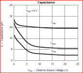
I don't think either the gate or the miller on those is big
enough to necessitate a cascode to divide those chores.
6,300,000uMho's transconductance doesn't need much
drive signal into the gate to swing the anti-triode, even
if that gate is 700pF. Reverse transfer is still only 14pF.
And enhancement mode no problem in this context.
Don't you have a handful of those 1700V IGBT's to burn?
IXGH10N170 - I think it was???
I don't think either the gate or the miller on those is big
enough to necessitate a cascode to divide those chores.
6,300,000uMho's transconductance doesn't need much
drive signal into the gate to swing the anti-triode, even
if that gate is 700pF. Reverse transfer is still only 14pF.
And enhancement mode no problem in this context.
kenpeter said:Michael, I don't see why bother with a two device cascode?
Don't you have a handful of those 1700V IGBT's to burn?
IXGH10N170 - I think it was???
I don't think either the gate or the miller on those is big
enough to necessitate a cascode to divide those chores.
6,300,000uMho's transconductance doesn't need much
drive signal into the gate to swing the anti-triode, even
if that gate is 700pF. Reverse transfer is still only 14pF.
And enhancement mode no problem in this context.
I believe you're right, there might only be minor differences in the
operating point and slight nonlinearity of the current mirror action
between a cascode and the single device. And I think in this circuit
Ciss is bootstrapped; Crss and Coss are not big problems.
It's a plate voltage regulator and a ripple filter and a power
doubler and a plate resistance divider.
Think about "problem" tubes like the 801A. You could use an
8K parafeed OPT and get 12-14 watts SE. Then you could use that
14K OPT for a practical 3C24 amp.
One big drawback is needing high voltage B+, but at least you're
getting output power out of the investment!
Michael
Attachments
If you take the output at midpoint R7 how does it simulate?
Someone else can do that! Just joking, will do a sim for you when I get home from work
. MJK, do you have any ideas of what value the two "source" resistors in the triode-antitriode configuration ideally should be? Reread the thread and found you presented the constantvoltage version already at page one
 .
. My main concern is if the internal caps of the DN2540 really shows up on the sims? I use the Supertex Spice model.
But at the moment my own interest is to find an "el cheapo" sand-replacement for an anodechoke.
revintage said:
Someone else can do that! Just joking, will do a sim for you when I get home from work
Thanks.
You can fake a depletion mode device in any of several ways....
And in the process, buffer out any excessive gate capacitance.
Especially effective when gate drive is bootstrapped to present
a very high pull-up impedance.
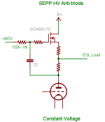
All MOSFETS (or IGBTs) shown are Enhancement types.
Didn't bother to draw a simple battery biased MOSFET,
but should be considered alongside these other choices.
I think Michael's latest anti-triode eliminates the need for
depletion mode anyway.
And in the process, buffer out any excessive gate capacitance.
Especially effective when gate drive is bootstrapped to present
a very high pull-up impedance.
All MOSFETS (or IGBTs) shown are Enhancement types.
Didn't bother to draw a simple battery biased MOSFET,
but should be considered alongside these other choices.
I think Michael's latest anti-triode eliminates the need for
depletion mode anyway.
Attachments
Hey kenpeter,
Whats wrong with an actual depletion mosfet? DN2540 is reliable and easy to deal with.
Did a few sims with the single DN2540 circuit of my last schematic and triode anti-triode with 2*390ohm and the only difference where that it added slightly more 3rd order distortion. Think it might only work when connected as CCS.
Well, driving a 100K load I wouldn't expect that much difference...
Driving a difficult load might be something else. Anti-triode helps
flatten the loadline seen by the plate (by half) for sure...
Gate capacitance might be ignored when the channel current is
constant. But its a factor for a load expected to be an active one.
Driving a difficult load might be something else. Anti-triode helps
flatten the loadline seen by the plate (by half) for sure...
Gate capacitance might be ignored when the channel current is
constant. But its a factor for a load expected to be an active one.
- Status
- This old topic is closed. If you want to reopen this topic, contact a moderator using the "Report Post" button.
- Home
- Amplifiers
- Tubes / Valves
- Anti-Triode SEPP, how to do best?