RC constant I see between the resistor that supplies 80V bias and bootstrapping cap.
In previously discussed case (my original Gyrator version) you were referring to there was a voltage divider that had lower resistance. Here you don't have it; you have a single resistor, and a huge leakage resistance that you can easily neglect.
In previously discussed case (my original Gyrator version) you were referring to there was a voltage divider that had lower resistance. Here you don't have it; you have a single resistor, and a huge leakage resistance that you can easily neglect.
RC constant I see between the resistor that supplies 80V bias and bootstrapping cap.
In previously discussed case (my original Gyrator version) you were referring to there was a voltage divider that had lower resistance. Here you don't have it; you have a single resistor, and a huge leakage resistance that you can easily neglect.
That's what I thought, but it doesn't seem to work that way. Lars mentioned the effect of the plate resistance for the tube, and that was reflected in his sims. If that's correct, then there's more to it than the voltage divider. I have to use a cap of 1uF or so, before the LF response is not affected. With a 1M resistor, I would expect it to be much lower. Color me mystified.
Sheldon
Last edited:
Lars mentioned the effect of the plate resistance for the tube, and that was reflected in his sims. If that's correct, then there's more to it than the voltage divider.
Hmm, did I say that
 ? I don´t recall it, could you please show me where? It seems like something wrong here.
6V6, 10Meg, 220k and 4.7u will give you a 5Hz cutoff with bypassed cathode resistor. With an unbypassed R you might need to double the cap value.
This is what I was referring to.
10mA might be a tad much through the LEDs. I usually go for ca 5mA.
Also noted the two bypass caps interact so check this. Maybe Wavebourn can shade some light on this?
And this.
Shed light upon bypassed LED...
What color would you prefer?
What has this to do with cutoff
frequency of the SEPP follower?
You are asking how any cathode
resistance from below might impact
plate resistance in network above?
Below cutoff of the cathode bypass
you would see the LED's resistance
curve, and a big phase shift...
I can't imagine cutoff of the SRPP
follower becoming significant before
cathode bypass is already a mess.
Last edited:
Shed light upon bypassed LED...
What color would you prefer?
What has this to do with cutoff
frequency of the SEPP follower?
You are asking how any cathode
resistance from below might impact
plate resistance in network above?
Below cutoff of the cathode bypass
you would see the LED's resistance
curve, and a big phase shift...
I can't imagine cutoff of the SRPP
follower becoming significant before
cathode bypass is already a mess.
Should have edited out the LED part. Nothing to do with the issue at hand. Don't think he's talking about LED cathode bias. These just set the voltage offset for the gyrator.
From the above quotes, it seems that the plate resistance affects the low frequency corner of the gyrator. That could explain why I need such a large cap. But?
Sheldon
I can't imagine cutoff of the SRPP
follower becoming significant before
cathode bypass is already a mess.
But, in the circuit I built, the bootstrap cap RC cut off seems related to the plate resistance. I say this because the required cap value makes sense referenced to the plate resistance, but makes no sense related to the voltage reference resistor. And Lar's comments seem to suggest this ("seem to suggest" - I certainly could be interpreting it wrong).
Another tidbit that may or may not shed light on the matter: I measure the voltage (80V) on the input side of the 1meg voltage reference resistor. I measure about 74V on the gate side. However, if I measure across the resistor, I get a couple of mV. I just assumed that the apparent drop with the first measurement was due to the meter error, related to the high impedance of the resistor interacting with the cap and the meter circuitry. Remember the circuit works and all the other values I've measured make sense (voltage on the output, g/s voltage for the FET's, etc.).
Sheldon
Sheldon,
Do you want the LTSpice files?
I can barely get components positioned on the screen where I want them in LTS. So with that background, is it a pretty simple matter to open the files and play - change components and look at the frequency response? If so, I would gladly accept the offer. I'll give it a try anyway.
Thanks,
Sheldon
Thanks Lars for the files. Anyone know of a good tutorial for LT Spice?
But before I got the files I set up a little test circuit as shown below, and made measurements. This is with a 3A5 tube, at about the same operating point as my output tube in the phono amp. With the cathode bypass cap in place, I get a -3dB point at about 25Hz. Unbypassed, I get about 60Hz.
But before I got the files I set up a little test circuit as shown below, and made measurements. This is with a 3A5 tube, at about the same operating point as my output tube in the phono amp. With the cathode bypass cap in place, I get a -3dB point at about 25Hz. Unbypassed, I get about 60Hz.
Attachments
Ah, it is not about time constant in gyrator; it is about quasi-inductive load of triode, so frequency response depends on inductive resistance and internal resistance of triode that due to feedback by current increases on Rk * (mu+1) value.
Thanks.
In the above case, the internal resistance is about 9k bypassed, and about 22k unbypassed. The F3's appear proportional to the internal resistance, but certainly not derived from plugging the internal R and bootstrap C into the usual formula. How do I account for the inductive resistance?
Practically, it's easy to just try a couple of cap values to get the needed bandwidth. I'm just curious as to how this works.
Sheldon
Thanks Lars for the files. Anyone know of a good tutorial for LT Spice?
LTSpice and What the New User Should Know - diyAudio
How do I account for the inductive resistance?
AFAIR, it is close to time constant multiplied by resistance of the resistor from source to output, if transconductance is infinite.
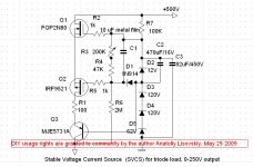
Here is what works like a charm; actually it is a gyrator. You may use MOSFETs here, or at least one on top to increase voltage divider's resistance and decrease capacitance needed.
It does not provide a constant current on DC. Actually, on DC it provides a constant voltage, but on AC it's dynamic resistance is huge.
[/QUOTE
That is absurdly cool!
I'm sure you've shown it before, but I only just now "got" it.
Even though I've used the higher voltage version of this circuit as a straight drop in several times (with great results) I still don't really get it. I see the base of Q2 staying at a fixed voltage and having the Vout adjusted by changing the operation of Q1 - but how does it work?. Would anyone be so Kind as to explain it?
Attachments
[/QUOTE
Would anyone be so Kind as to explain it?
I'll try. Start with Q1, R1, R2, and R3. Connect R3 to ground. With that you have a basic current source, as the voltage drop across R1 is kept constant (subject to the power supply ripple).
Add C1 and connect R3 to the plate. Now you have a basic gyrator. The voltage divider now is referenced to the plate for DC, but C1 keeps the voltage across R2 constant for AC changes at the plate.
Add Q2, D and R4. Now you have isolated the drain of Q1 from variations at the plate. This makes the basic gyrator into a high performance gyrator.
Sheldon
- Status
- This old topic is closed. If you want to reopen this topic, contact a moderator using the "Report Post" button.
- Home
- Amplifiers
- Tubes / Valves
- Anti-Triode SEPP, how to do best?