Hi Eva, I think you missed the point of why jbau added the very small resistance in series with the output of the reg. It was not for stability or to damp the resonance, it was to flatten the phase of the output impedance of the reg.
Being before the output cap it is forming an rc lp filter which helps to flatten out the phase. Jbau believed this helped with subjective things like imaging.
Tony.
Being before the output cap it is forming an rc lp filter which helps to flatten out the phase. Jbau believed this helped with subjective things like imaging.
Tony.
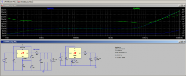
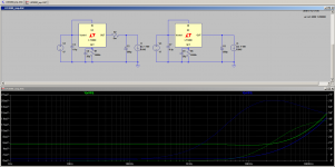
Ok since I said I was pursuing the LT3080 now, I thought I'd post a couple more sims to show why. This is compared to the sims with the LT1086 in jbau's configuration (without the 10uF and 100nF because it makes it easier to see what is going on with the phase and impedance).
The models are the ones that come with LTSpice. Whether the LT3080 model is to be trusted I don't know but it seems to leave the LM1086 in the dust (perhaps the model is a little too perfect....) even if I build it I won't know because I can't do these measurements, but it looks promising")
Tony.
The models are the ones that come with LTSpice. Whether the LT3080 model is to be trusted I don't know but it seems to leave the LM1086 in the dust (perhaps the model is a little too perfect....) even if I build it I won't know because I can't do these measurements, but it looks promising
Tony.
Attachments
Last edited:
Bruce, post 382 was the original comparison. The sims correlated well with what jbau reported. I just added in the diekman mod to compare, as I was interested to see if it made any difference, which it did.
Post 387 was done purely to show the effects of ESR in the output cap on the LM317 and was not supposed to be representative of jbau's circuit at all (jbau abandoned use of the LM317 completely by that stage). with the 20m Ohm in circuit the resonance is not removed it is just masked, hence taking the resistance out to better show the presence of the resonance.
...Just for completeness I have just added them with complete guesses for ESR. 10uF with 0.001 ohms ESR and 30nH ESL, 100nF with 0.001 ESR and 10nH ESL It makes very little difference at all in the audio band, so for the purposes of what I was showing I think it is close enough to say that the omission was not an issue, especially since jbau only showed data from 100Hz to 20Khz.
You may be interested to see what effect those extra caps have on the impedance at higher frequencies (again the ESR data for those extra caps was made up and is not really valid) in all cases green is with 560uF cap only and blue is with additional 10uF film and 100nf.
Sorry that I missed that in post 382... got thrown off the the Jbau label on the 387 chart and should have looked closer at earlier posts. Interesting results, and thank you for trying and showing the results of those various sims.
When you say the rbuffer resistor 'masks' the resonant hump, you mean that it is naturally there in the reg's output and so should be noted... but the rbuffer resolves it in real-world use, right?
Ok since I said I was pursuing the LT3080 now, I thought I'd post a couple more sims to show why. This is compared to the sims with the LT1086 in jbau's configuration (without the 10uF and 100nF because it makes it easier to see what is going on with the phase and impedance).
The models are the ones that come with LTSpice. Whether the LT3080 model is to be trusted I don't know but it seems to leave the LM1086 in the dust (perhaps the model is a little too perfect....) even if I build it I won't know because I can't do these measurements, but it looks promising
I look forward to hearing of the results of your build -- hear if there are sonic differences to be found!
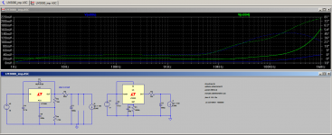
Hi Bruce, It definitely reduces the resonant peak but doesn't eliminate it, which I think is one of the reasons jbau ended up writing it off. You can get rid of the resonance with enough esr in series with the output cap but at the cost of increased impedance at higher frequencies (I used 0.33 ohms in my LM317 based supply)
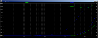
Sim below shows the blue without the 20m ohm and green with it. You can see the hump is still there with the 20m ohm but no where near as pronounced. I think that this hump is the one jbau referred to at "around 6Khz"
2nd attachment compares green curve 560uF output cap 0.04 ESR with blue 560uF output cap 0.2 ESR No 20m Ohm output resistor, just to show that the extra esr on the cap damps the resonance.
I'm not sure if I will be able to pick any sonic differences (some things I notice others I don't.. But don't hold your breath, I'm rather infamous for taking a long time to get from concept to realization
Tony.
Attachments
Last edited:
Ok since I said I was pursuing the LT3080 now, I thought I'd post a couple more sims to show why. This is compared to the sims with the LT1086 in jbau's configuration (without the 10uF and 100nF because it makes it easier to see what is going on with the phase and impedance).
The models are the ones that come with LTSpice. Whether the LT3080 model is to be trusted I don't know but it seems to leave the LM1086 in the dust (perhaps the model is a little too perfect....) even if I build it I won't know because I can't do these measurements, but it looks promising
Looking over the '3080's datasheet, I noticed a few things:
1. One must use very large resistors for R1 in order to get higher voltages out. I calculate 12M ohms for 12V output, but I could certainly be wrong.
2. C8 can be any value up to 1uF.
3. A 1N4148 diode can be placed across the IN/Vc and Set pins for "soft startup".
Tony, have you tried different value low-ESR output caps to see if it makes any difference?
Also, what is the purpose of R2 in your circuit? Is this a ESR figure for the 680uF cap?
Looking over the '3080's datasheet, I noticed a few things:
1. One must use very large resistors for R1 in order to get higher voltages out. I calculate 12M ohms for 12V output, but I could certainly be wrong.
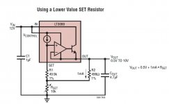
I calculate 1.2MΩ for 12V output. On the data sheet, page 17, the figure titled "Using a Lower Value SET Resistor" shows how to reduce the resistor value.
I calculate 1.2MΩ for 12V output. On the data sheet, page 17, the figure titled "Using a Lower Value SET Resistor" shows how to reduce the resistor value.
Yeah, my bad. I put one extra zero in 10uA.
I'll check out page 17.
Thanks for the correction.
Oh, sorry to disturb your subjective audio thread. I was explaining how to obtain the lowest ringing-free output impedance from the smallest-size and longest-life parts, this is called industrial design.
Nothing wrong with a little "industrial design" input.
Hi Eva, input is definitely appreciated! The direction the thread took is not obvious from the title as well.
The OP had the goal of achieving low output impedance, as flat as possible though the audio band, with as flat as possible phase as well.
This was his goal from the beginning. in the end he found he couldn't do this with an LM317 without increasing the output impedance to at least 50m ohms which he deemed unacceptable. He then decided to abandon the LM317 and used the LT1085.
I believe that it was the ringing that you are providing a solution for that was the reason he could not achieve his goal with the LM317, whilst your solution fixes that problem, it doesn't achieve his primary goal
Whilst his goals were based on his belief that it made a subjective difference in the sound achieved, I don't think that you could argue that a low, flat output impedance with very little phase shift is a bad thing in a power supply. You could argue that it doesn't really matter much, but you would have a much harder time arguing that it made things worse (provided no other issues are introduced in achieving it).
Tony.
Hi ammel68,
1. yes large resistors required and there are potential other issues with noise pickup due to the very low current (10uA). There are other ways of mitigating this though (with added complexity in the circuit).
2. I haven't got the datasheet handy. but I assume you mean the set pin bypass. 20pF seems to be all that is needed (if at all) bigger values probably not necessary.
3. I'd missed that, but probably not necessary with most low current supplies.
Which post was the R2 in? I posted so many different sims
Tony.
Hi ammel68,
1. yes large resistors required and there are potential other issues with noise pickup due to the very low current (10uA). There are other ways of mitigating this though (with added complexity in the circuit).
2. I haven't got the datasheet handy. but I assume you mean the set pin bypass. 20pF seems to be all that is needed (if at all) bigger values probably not necessary.
Which post was the R2 in? I posted so many different sims
Hi Tony,
The first photo shows what the datasheet states about cap size across Rset:
The second photo shows R2 in one of your simulations.
The third photo shows one solution for using lower value resistors/trimmer pots from the datasheet as pointed out to me by Bill P..
What are your thoughts about this solution?
Have you simulated what effect a smaller(say 220uf or 470uF) output cap has on performance?
Thanks.
Attachments
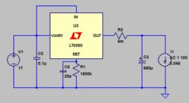
OK. r2 is based on jbau's experiments where putting a small amount of series resistance at the output of the reg flattens out the phase of the impedance.
I tried various values on the rset cap, and in the sim I couldn't see any tangible difference, but I wasn't testing transient response. I was only looking at ripple and output impedance. I did find that in certain configurations (the third image you attached being one of them) that the circuit would oscillate if you didn't have at least 20p on the rset pin.
I tried the third pic in the sim and it resulted in substantially higher ripple on the output, whether or not it was high enough to be of concern however is another matter. I'd have to go back and run it again to find out.
The avenue I am going down at the moment is one of the other solutions of providing a CCS of 1ma to the rset pin (allowing a 10K resistor to be used for 10V output), that seems to be better from a ripple perspective, but increases complexity.
Another option is to use a precision voltage reference, eg 5V or 10V applied direct to the rset pin. This also works well (in the sim) but I can't find any higher than 10V.
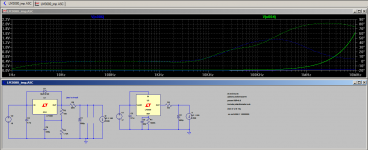
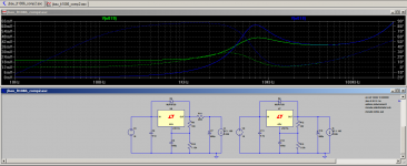
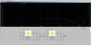
Attached is a sim showing the difference between having the 5mOhm (R2) resistance on output (green) and without blue.
2nd attachment is a closer look at what is happening which indicates that the combo of R2 and the output cap is not ideal, resulting in a slight dip in the impedance.
The effect (of R2) on the overall impedance of the circuit is fairly obvious, it is the phase change that is the main thing that jbau was aiming for, making the phase flatter through the audio band. Whether this is worth pursuing, at the expense of increase output impedance, I'm not sure, but I thought it was worth experimenting with.
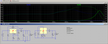
Third pic shows difference between using the 560uF cap (green trace) and 220uF (blue trace) I'm not sure what is causing the dip with the 560uF. Also the magnitude of this dip is very small, 0.3mOhms approx. In the world of sims it shows, but once you bring component tolerances into the equation and also trace resistances etc the sim will not reflect reality... I find it interesting none the less. I'm learning stuff as I go.
edit: just did a comparison 4th image between 1.5M on set pin and using the simple ccs in the third image of ammel's post. tick is 100uV resistors in the crc are 2 ohm. Note that the current in that sim was 240mA (didn't realize when I ran it).
Tony.
I tried various values on the rset cap, and in the sim I couldn't see any tangible difference, but I wasn't testing transient response. I was only looking at ripple and output impedance. I did find that in certain configurations (the third image you attached being one of them) that the circuit would oscillate if you didn't have at least 20p on the rset pin.
I tried the third pic in the sim and it resulted in substantially higher ripple on the output, whether or not it was high enough to be of concern however is another matter. I'd have to go back and run it again to find out.
The avenue I am going down at the moment is one of the other solutions of providing a CCS of 1ma to the rset pin (allowing a 10K resistor to be used for 10V output), that seems to be better from a ripple perspective, but increases complexity.
Another option is to use a precision voltage reference, eg 5V or 10V applied direct to the rset pin. This also works well (in the sim) but I can't find any higher than 10V.
Attached is a sim showing the difference between having the 5mOhm (R2) resistance on output (green) and without blue.
2nd attachment is a closer look at what is happening which indicates that the combo of R2 and the output cap is not ideal, resulting in a slight dip in the impedance.
The effect (of R2) on the overall impedance of the circuit is fairly obvious, it is the phase change that is the main thing that jbau was aiming for, making the phase flatter through the audio band. Whether this is worth pursuing, at the expense of increase output impedance, I'm not sure, but I thought it was worth experimenting with.
Third pic shows difference between using the 560uF cap (green trace) and 220uF (blue trace) I'm not sure what is causing the dip with the 560uF. Also the magnitude of this dip is very small, 0.3mOhms approx. In the world of sims it shows, but once you bring component tolerances into the equation and also trace resistances etc the sim will not reflect reality... I find it interesting none the less. I'm learning stuff as I go.
edit: just did a comparison 4th image between 1.5M on set pin and using the simple ccs in the third image of ammel's post. tick is 100uV resistors in the crc are 2 ohm. Note that the current in that sim was 240mA (didn't realize when I ran it).
Tony.
Attachments
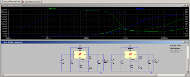
Tony, in your fourth image comparing the simple CCS with just a resistor for Rset, which one is green and which is blue?
I'm having trouble following some of these comparisons since I'm not sure exactly what they're showing.
In the fourth image, the blue result "looks" much better to me than the green.
Is this indeed the case or am I misinterpreting the results?
Also, if larger output caps aren't going to provide any additional benefit, why use them?
Not sure about the LT3080, but I thought using large caps on LM-series regs can cause all sorts of problems.
I was instructed by other members to use no more than 100uF output caps on those regs.
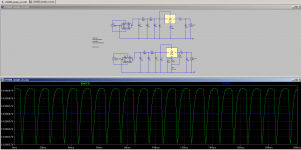
Sorry I didn't specify which trace was which. Blue is with just the 1.5Mohm resistor and green is with the simple CCS. This is the ripple which makes it through the regulator, and yes the blue is a much better result!
Bigger output caps can help with transient response (ability to cope with large transient current reqirements). jbau thought that the size of the cap had an effect on imaging, this is something that can't be objectively tested.
Yes big caps (because they tend to be lower ESR) can cause problems on an LM317 (that is what the earlier sims I posted of the LM317 were demonstrating, ie the lump in the impedance curve. The problem is that the output inductance of the regulator combined with the capacitance of the output cap form a tuned circuit which resonates. The bigger the cap the lower the resonant frequency (right into the audio band).
I used a 1000uf cap on my LM317 circuit, but I had 0.33 ohms resistance in series to ground, and it is completely stable (as far as I can tell using my scope). I wouldn't use this approach in future though.
Tony.
Sorry I didn't specify which trace was which. Blue is with just the 1.5Mohm resistor and green is with the simple CCS. This is the ripple which makes it through the regulator, and yes the blue is a much better result!
That looks quite good for only one resistor.
Is there a problem with using the regulator with only one large value resistor vs. the higher ripple circuit below it with 3 resistors and the 20pF cap?
I find it odd that Linear would recommend the 3 resistor and one cap circuit with it having so much ripple, don't you?
Hi Ammel, I'm going to start another thread for this as we are diverging too much from the original topic. But in the interim, the answer is that Linear assumes better engineering that what I showed in that sim I'll elaborate further in the new thread. It might take me a little while to get it all together though.
Tony.
I'll elaborate further in the new thread. It might take me a little while to get it all together though. Tony.
- Status
- This old topic is closed. If you want to reopen this topic, contact a moderator using the "Report Post" button.
- Home
- Amplifiers
- Power Supplies
- Another look at the LM317 and LM337 regulators