You may want to also have a read of the following interview (from 1988) https://www.stereophile.com/interviews/694/index.html It seems that jbau was a (the) pioneer in discovering the importance of phase matching in speaker crossovers, something that we take for granted today.
edit: this thread actually steered me down the path of using two LM317's instead of a positive and a negative reg when I was designing the power supply for my Synergy active crossover. I didn't chase the flat impedance flat phase, just the symmetry (as using the same reg for positive and negative seemed to be the simplest way to get well matched rails, something that jbau couldn't do with the existing circuit he was modding), I wonder how implementation specific the conjugate network on the output is. Without the means to measure the result it would be a bit hit and miss I think.
Tony.
Last edited:
So now the LM337 sucks and it's better to use two '317s instead??
Maybe so for some folks, but I'm quite happy with the SQ from using the LM317 and LM337 to power my simple low-gain op-amp line stage circuits.
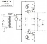
Having tried several other designs, including the Apex design below, I still prefer the sound of a LM317/337 supply with lower value caps for Cout and Cadj..
I'm currently working on assembling a pair of Jung/Didden super regulator boards, which I purchased from the DIY Store, to see how they compare to my good 'ole LM317/337 boards.
Maybe so for some folks, but I'm quite happy with the SQ from using the LM317 and LM337 to power my simple low-gain op-amp line stage circuits.
Having tried several other designs, including the Apex design below, I still prefer the sound of a LM317/337 supply with lower value caps for Cout and Cadj..
I'm currently working on assembling a pair of Jung/Didden super regulator boards, which I purchased from the DIY Store, to see how they compare to my good 'ole LM317/337 boards.
Attachments
hehe, i designed the PS back in 2010, I revisited the sims when this thread popped up again. There are a few things I would change now.
The interesting thing about this thread is that the 337 was touted as being better than the 317 (and for matching purposes jbau paired it with a totally different +ve reg), but everything else I have ever read says exactly the opposite (ie the 317 is better performing than the 337).
However I think that "better" in the case of this thread was to do with jbau's goals of impedance and phase flattening/matching.
I also recently took at look at the super reg's in the diyaudio store. I might go down that path at some point... I'm a bit skeptical as to whether I would be able to hear a difference myself though.
Tony.
The regulator's output impedance (magnitude and phase) will vary with load current, so if you consider the actual load being driven to be "implementation", then: quite a bit. You could of course swamp this out and make a more universally-applicable recommended implementation, by either connecting extra elements in parallel with the load (raising the power dissipation) or connecting extra elements in series with the regulator (raising the magnitude of the output impedance). I did a conceptually similar thing with power transformer snubbers, which completely swamps out secondary capacitance and rectifier capacitance; it works well in simulation and in real world practice.I wonder how implementation specific the conjugate network on the output is.
I have a feeling that different manufacturers of "LM317" ICs are shipping chips with not-identical output impedance, magnitude and phase. The device is so old, and has been cost-reduced so many times (moving it from process "N" which is being decommissioned, to process "N+1"), that each manufacturer's current LM317 is a great-great-granddaughter of the NSC original. And there is probably a lot of diversity between them. So you'd need to characterize the output impedance for each manufacturer, individually. Or just pick one and hope you can source from them forever.
If you believe that constant phase of impedance is supremely important, it is probably a lot easier to achieve this in a discrete regulator rather than an IC like the LM317. Among other advantages, you know with 100% certainty what is inside! You can choose to employ only those circuit topologies that you feel are accurately simulated in LTSPICE, and then simulate (rather than measure) your regulator's output impedance, magnitude and phase. Presto, conjugate network design and better still, conjugate network verification and certification, before you ever send your first PCB to fab. And then tweaking and tinkering in the lab are 1000% easier because you have access to all internal nodes as Test Points.
One of my points in my earlier post is that any two types of positive and negative regulators are almost certainly not identical, and with separate secondary windings you can use whichever one you think is "best" for both the positive and negative regulator.So now the LM337 sucks and it's better to use two '317s instead??
One of my points in my earlier post is that any two types of positive and negative regulators are almost certainly not identical, and with separate secondary windings you can use whichever one you think is "best" for both the positive and negative regulator.
So in this case, the '317 is considered the better of the two?
@Mark -- good point -- for the regulator bake-off I used new Fairchild 317/337's.
What is the regulator bake-off?
One of my points in my earlier post is that any two types of positive and negative regulators are almost certainly not identical, and with separate secondary windings you can use whichever one you think is "best" for both the positive and negative regulator.
I'm pretty sure that post was the one that clinched it for me to do a design with two positive regs
from my blog:
The someone I suspect was you benbOne useful thread here on diyAudio was this one from Fred DieckMann. Post 34 in that thread is what the LM317 part of my circuit is based on. Another one was This thread from jbau, although it steered me in the direction of NOT using a negative regulator at all. The thing that struck me was his subjective evaluation that symmetry in the supply rails made a big difference to the sound of the amplifier. One person commented why don't you just use two LM317's (which in his application wasn't possible) but for me the decision was clear
ammel68 best is a relative term. For what jbau was trying to achieve he believed that the 317 was best, early on that was due to some errors in measurement that made it appear to have a much flatter impedance than it actually did. Later it was because he found it had a very similar output impedance to another regulator (the LT1085)
benb's suggestion makes the most sense (IMO) if matching is important. The reason jbau coudn't do that was because he was trying to modify existing power supply's NOT designing one from scratch.
So in that context, benb's suggestion is use two of whatever reg, be it positive or negative, which you think is best!
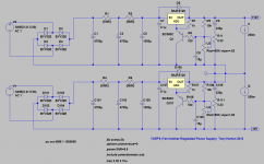
It is actually very simple. You create two identical power supplies. Run them off separate transformer windings and bridge rectifiers, tie what would normally be the ground of the first one to the output of the second one, and what would normally be the ground on the second one becomes your -ve rail. example attached (revised version of my original yarps ps now that I'm a bit wiser... still overkill though
) edit: Note that this is a bit OT from the original idea in this thread, as it does not have the very flat impedance and phase that jbau was aiming for, it does however meet the symmetry aspect very well (I think). Tony.
Attachments
Last edited:
The original source of the bc560 idea is here http://www.diyaudio.com/forums/powe...ing-lm3x7-regulator-circuit-2.html#post356154
I originally had a 4.7uF on the adjust to ground (and is what I implemented in the real circuit), but recent sims seem to indicate increasing to 15uF has some benefit, past that there are diminishing returns. Note that there have been many other proposed "better" lm317 circuits. This was just what I decided to implement.
Tony.
Last edited:
What is the regulator bake-off?
Never mind. I didn't realize "jackinnj" and "John Walton" are one and the same:
https://linearaudio.net/authors/353
I've already purchased and read John's Linear Audio regulator "bake-off" article where the Jung/Didden regulator came out on top.
I'm in the process of assembling my Jung/Didden boards from the DIY Store to see how they sound compared to my '317/337 boards I'm currently using for op-amp circuits.
Mark, I don't know if it is important or not I tend to subscribe to the, "if it might make a difference, and isn't difficult/expensive to do then why not have a go camp".
I used LT317A's as supposedly they are a premium version with tighter tolerances... you pay for it though! They are more than 4 times the price of the cheapest LM317's but still at around $4.50 it isn't that expensive.
This thread has piqued my interest again, and I might actually make a proper pcb for my circuit rather than the verro board prototype I'm still using at the moment.
I wish I had the measurement gear to do lots of tests but unfortunately I only have rudimentary equipment.
Tony.
I tend to subscribe to the, "if it might make a difference, and isn't difficult/expensive to do then why not have a go camp". I used LT317A's as supposedly they are a premium version with tighter tolerances... you pay for it though! They are more than 4 times the price of the cheapest LM317's but still at around $4.50 it isn't that expensive.
This thread has piqued my interest again, and I might actually make a proper pcb for my circuit rather than the verro board prototype I'm still using at the moment.
I wish I had the measurement gear to do lots of tests but unfortunately I only have rudimentary equipment.
Tony.
Certainly an option (or one of the newer LT series chips) (although I'm pretty sure the early thoughts around the LM337 superiority turned out to be measurement error, something to do with a 10000uF cap that was being swapped from one circuit to the other and not discharging properly from memory, but I can't find the post...) .
I found with the bc560 in play (in the sims) the impedance flattening that jbau used doesn't seem to have much effect, so an other wise bog standard LM337 circuit doubled up should do the trick, but as I said I'm not sure that the 337 was any better than the 317 other than it matched well in jbaus measurements with the LT1085.
Tony.
Last edited:
I found with the bc560 in play (in the sims) the impedance flattening that jbau used doesn't seem to have much effect, so an other wise bog standard LM337 circuit doubled up should do the trick, but as I said I'm not sure that the 337 was any better than the 317 other than it matched well in jbaus measurements with the LT1085.
That's interesting, can you unpack that slightly? You mentioned that your measurement gear is 'rudimentary'. So does that mean you listened to a JBau-based PSU and found that it sounded no better than the Dieckman rec'd bc560 circuit, or what are you referring to?
This thread has piqued my interest again, and I might actually make a proper pcb for my circuit rather than the verro board prototype I'm still using at the moment.
If you do decide to make a board, I hope you can post it here for myself and others to view.
There are some people here that are very good at board layout and may offer some constructive criticism.
If I'm not mistaken, you're one of the people that helped me with my '317/'337 layout a while back.
brucew268, no I haven't built jbau's version. I have just simmed some of the mods he did (both on the standard reg configuration and on the dieckman version. On the dieckman version the adjust pin mods have very little effect on the output impedance, I also wasn't able to get much effect using the LR on the output either, though that may require more experimentation.
What I have built is an earlier version of the circuit I posted above. Main differences were I had 3.3 ohm resistors in both the supply and return lines, recent sims show that the resistance in the return lines makes the lower half very sensitive to small resistance in the output, with output inpedance increasing significantly below 100Hz. So as was questioned at the time it wasn't such a good idea!
The other difference is I dropped the output caps from 1000uF (with a 470nf parallel) to 330uF. With the 1000uF the sim was not stable unless I added the 470nf in parallel. That should have told me something The sim is stable with the 330uF and the output impedance is almost identical to with a 1000uF.
One other interesting thing of note. The impedance peaks that jbau talks about with the LM317, do not occur with the dieckman circuit provided there is some series resistance in series with the output cap (again in simulation as I can't measure the output impedance in the real circuit).
edit: it seems from jbau's comments that the mods in his experience, have an effect on the imaging (ie soundstage). So regardless of measurement equipment available the final test will be a subjective one.
Tony.
What I have built is an earlier version of the circuit I posted above. Main differences were I had 3.3 ohm resistors in both the supply and return lines, recent sims show that the resistance in the return lines makes the lower half very sensitive to small resistance in the output, with output inpedance increasing significantly below 100Hz. So as was questioned at the time it wasn't such a good idea!
The other difference is I dropped the output caps from 1000uF (with a 470nf parallel) to 330uF. With the 1000uF the sim was not stable unless I added the 470nf in parallel. That should have told me something
The sim is stable with the 330uF and the output impedance is almost identical to with a 1000uF. One other interesting thing of note. The impedance peaks that jbau talks about with the LM317, do not occur with the dieckman circuit provided there is some series resistance in series with the output cap (again in simulation as I can't measure the output impedance in the real circuit).
edit: it seems from jbau's comments that the mods in his experience, have an effect on the imaging (ie soundstage). So regardless of measurement equipment available the final test will be a subjective one.
Tony.
Last edited:
Very helpful, thanks!brucew268, no I haven't built jbau's version. I have just simmed some of the mods he did (both on the standard reg configuration and on the dieckman version. On the dieckman version the adjust pin mods have very little effect on the output impedance, I also wasn't able to get much effect using the LR on the output either, though that may require more experimentation.
What I have built is an earlier version of the circuit I posted above. Main differences were I had 3.3 ohm resistors in both the supply and return lines, recent sims show that the resistance in the return lines makes the lower half very sensitive to small resistance in the output, with output inpedance increasing significantly below 100Hz. So as was questioned at the time it wasn't such a good idea!
The other difference is I dropped the output caps from 1000uF (with a 470nf parallel) to 330uF. With the 1000uF the sim was not stable unless I added the 470nf in parallel. That should have told me something
One other interesting thing of note. The impedance peaks that jbau talks about with the LM317, do not occur with the dieckman circuit provided there is some series resistance in series with the output cap (again in simulation as I can't measure the output impedance in the real circuit).
edit: it seems from jbau's comments that the mods in his experience, have an effect on the imaging (ie soundstage). So regardless of measurement equipment available the final test will be a subjective one.
Tony.
- Status
- This old topic is closed. If you want to reopen this topic, contact a moderator using the "Report Post" button.
- Home
- Amplifiers
- Power Supplies
- Another look at the LM317 and LM337 regulators