It might be but don't quote me on that. I'm no expert, but I can make a general observation. Just the fact that there are more types of positive regulators made (because there are so many single-voltage applications, with virtually all using a negative-referenced ground - for single-supply analog as well as digital applications), it's more likely that the "best" one will be among the positive regulators. But I'll defer to the actual testing that others are discussing here.So in this case, the '317 is considered the better of the two?
I'll take whatever credit I can get!I'm pretty sure that post was the one that clinched it for me to do a design with two positive regs")
from my blog: The someone I suspect was you benb
I've been doing some sims, using the LT1086 and also the LT317 and it has been quite interesting. One thing that had bugged me about jbau's results was that even though he was using large low esr caps on the output he didn't appear to be getting any resonance problems.
I also discovered that LTSpice does not take load resistors into account when doing AC analysis so the results being displayed when I did impedance tests were basically unloaded. Putting a dc component in of 0.045A which is the current jbau was testing with (330 ohm load resistor on 15V supply) the resonance disapeared (at least with the LT1086) with the LM317 it is there which is the hump that he was talking about when using the LM317.
Interestingly though dropping the current down to 10mA shows a strong resonant hump in the impedance even with the LT1086. It's completely gone by 45mA though.
What is even more interesting is that the impedance flattens out more (as does the phase) with increasing current. I can go to 240mA before the sim goes wacko. I suspect it is an issue with the current handling of the LT models.
The diekman mod doesn't make much difference except in one key area. The adjust cap can be MUCH smaller and still have superior phase at the low frequencies with the Diekman mod. 15uF cap vs 330uF cap in the jbau version.
I found that with 200mA load that 5mOhm resistance on the output flattened out the phase nicely also resulting in a much flatter overall impedance almost all the way to 20Khz and what I think is a better phase curve as well. That's great for me because the ciruit I'm powering draws about 250mA but I guess you could just add in some additional load resistors and burn extra watts to get it more linear.
Well if the sims can be trusted of course. Certainly the results with the standard circuit which jbau posted seem to correlate well with the measurements he posted.
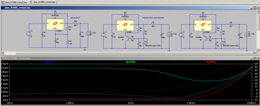
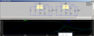
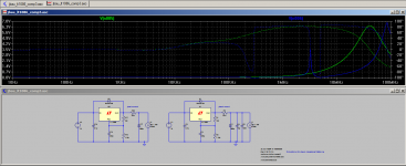
Attached is an image from the sim. Blue trace is jbau's circuit as per post #248 (without the paralell 10uF film and 100nF caps) green trace is the same circuit but with the Diekman mod and 15uF cap instead of 330uF cap on the adj.
Red trace is with the Diekman mod and only 5m ohms on the output. Note that doing the same on jbau's circuit with 200mA load gives very similar results with slightly worse phase at the low frequencies.
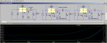
In the second plot I compare the results when using a 15uF cap on adjust with both the Diekman and standard jbbau circuit.
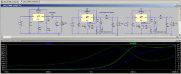
The third plot shows what happens when the current is dropped to 20mA (still with the 5mOhm output resistance). The resonance with the output cap is starting to show through, interestingly it is more of a problem with the Diekman mod.
Anyway that's probably enough for one post!
Tony.
I also discovered that LTSpice does not take load resistors into account when doing AC analysis so the results being displayed when I did impedance tests were basically unloaded. Putting a dc component in of 0.045A which is the current jbau was testing with (330 ohm load resistor on 15V supply) the resonance disapeared (at least with the LT1086) with the LM317 it is there which is the hump that he was talking about when using the LM317.
Interestingly though dropping the current down to 10mA shows a strong resonant hump in the impedance even with the LT1086. It's completely gone by 45mA though.
What is even more interesting is that the impedance flattens out more (as does the phase) with increasing current. I can go to 240mA before the sim goes wacko. I suspect it is an issue with the current handling of the LT models.
The diekman mod doesn't make much difference except in one key area. The adjust cap can be MUCH smaller and still have superior phase at the low frequencies with the Diekman mod. 15uF cap vs 330uF cap in the jbau version.
I found that with 200mA load that 5mOhm resistance on the output flattened out the phase nicely also resulting in a much flatter overall impedance almost all the way to 20Khz and what I think is a better phase curve as well. That's great for me because the ciruit I'm powering draws about 250mA
but I guess you could just add in some additional load resistors and burn extra watts to get it more linear. Well if the sims can be trusted of course. Certainly the results with the standard circuit which jbau posted seem to correlate well with the measurements he posted.
Attached is an image from the sim. Blue trace is jbau's circuit as per post #248 (without the paralell 10uF film and 100nF caps) green trace is the same circuit but with the Diekman mod and 15uF cap instead of 330uF cap on the adj.
Red trace is with the Diekman mod and only 5m ohms on the output. Note that doing the same on jbau's circuit with 200mA load gives very similar results with slightly worse phase at the low frequencies.
In the second plot I compare the results when using a 15uF cap on adjust with both the Diekman and standard jbbau circuit.
The third plot shows what happens when the current is dropped to 20mA (still with the 5mOhm output resistance). The resonance with the output cap is starting to show through, interestingly it is more of a problem with the Diekman mod.
Anyway that's probably enough for one post!
Tony.
Attachments
Last edited:
I have been experimenting with LM317L for 3.3V for a MCU and as a 3.3V reference (through gentle LPF) for audio circuits, as it still happens to be the best low cost linear regulator. SMD multi-layer board. Ceramic capacitors. The 32 bit 96Mhz MCU draws 60mA pulses with very fast edges when it is operated in "low power mode" as it comes from sleep/wait momentarily to execute timer interrupt code, and then goes back to sleep/wait drawing very little current. This turns into excellent test setup for regulator performance.
I found that LM317L at 3.3V, with gentle Cadj cap (10uF, but also happens with less) requires at least 47uF and 0.2ohms ESR of output decoupling for stability. Oscillation frequency when this criteria is not met is between 20khz and 50khz, worse at lower load, worse with lower in-out voltage difference.
For higher output voltages the minimum output capacitance value is reduced, the minimum ESR is kept. 22uF and 0.2r total ESR is OK for 11V out.
At much higher output capacitance there is no ESR requirement.
It just happens than the regulator is high gain, and when the loop crossover frequency is moved too high it requires a zero (C in series with R) for enough phase margin. With higher capacitance values the loop crossover frequency is moved down and the zero is no longer needed.
Hi Eva, yes my earlier sims indicated the lm317 needs some additional series resistance to be well behaved. Even with big caps, but that is in sims, I can't do the real world output impedance measurements.
I need to do some more sims with the new LT317 model I have, as it appears to be behaving a little differently to the model I had before.
What I am seeing though is that the LT1086 seems to be better behaved, and also gives flatter output impedance much further out in frequency than what the LM317 does (without any tweaks), which is pretty much what jbau's real world measurements indicated as well.
Tony.
Tony, since the LT1086 is available in fixed voltages up to 12V, wouldn't that eliminate the trimmer pot or resistance divider required for the adjustable LM317?
Just looking at it from a "less parts on the board" perspective.
Perhaps you can do some more simulations with the required output cap. The Linear datasheet states that it's stable with only a 10uF cap.
For my simple LM317/337 boards, I'm currently using 22uf adj. caps and 10uf output caps. Both are NOT low ESR, since I was instructed in another thread that using low ESR caps is a no-no with the LM regulators and can lead to oscillations.
Yes if there is a version which matches the voltage you need then that can be used, I just used the adjustable version, as jbau's original tests were at 15V output, and my own circuit is 10V.
The sims I have been doing have always shown resonance problems with the LM317, that hasn't changed, but it does seem the issue is less (but not gone) with higher current draw. Definitely safest to not use low esr caps!
I originally considered the LT1085, but for some reason at the time decided to go with the 317, I don't remember the reason. I think that the 1085/1086 look like very worthwhile options compared to the 317, but if cost was the ultimate decider, the 317 can't really be beaten.
Tony.
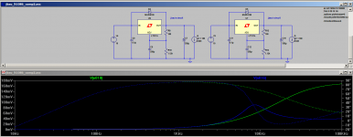
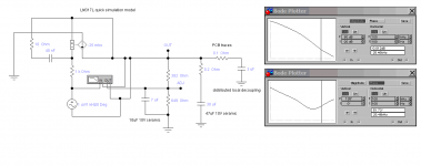
Attached is an example of low esr 330uF on the output (0.04 ohms esr) blue trace, compared to 330uF with 0.2 ohms ESR green trace for LT317. I dropped the output cap to 330uF for this demonstration as it makes the resonance clearer.
This is with no series resistance in the output. Current 45mA as per jbau's other tests.
With 560uF the peak is a lower and broader and pretty close to the 6Khz that jbau mentioned. The second image shows the 330uF blue and 560uF green.
The first plot clearly shows that the higher ESR tames the resonance but at the expense of much higher rising impedance with frequency. It is this that has made me think that moving to the LT1086's is a good idea.
Tony.
Attachments
- LTxxx parts are expensive and improved and do not necessarily represent behavior of low cost LM317L from TI, National or ST.
- LTSpice is not the simplest approach to simulate linear voltage regulators, the power of this software is simulating switching power conversion.
- Electrolytic capacitors are programmed obsolescence. Values as high as 500uF are not practical in ceramics. So in the end the challenge is finding the way to make it well behaved with reasonably sized ceramics. In other words: finding the lowest cost option to get a circuit with the minimum set of features and no practical drawbacks.
A LM317L open loop gain simulation model obtained directly from prototype is attached. The added 0.2r is the trick to get it stable. The 0.1r are PCB traces.
Attachments
Last edited:
What simulation software is that Eva?
Not sure whether you have read the whole thread.... The main jist of what the OP was aiming for was trying to get the flattest impedance and phase out of the LM317 (at 15V), in the end he moved to the LM1805 for reasons demonstrated by the sims I posted above (though he did real measurements of the output impedance with a network analyser, which correlate pretty closely to the results I got with LTspice)...
One thing that I don't think anyone has mentioned yet in this entire thread is the noise level on the output of the LM317 (LT1086 is comparable)... it is nearly 300uV RMS.... I'm going to have a play with some sims of the low noise regs as well (40uV RMS noise types). Though jbau did state that noise and other characteristics were of secondary importance to him and linear phase and output impedance were what he was chasing.
Tony.
- LTSpice is not the simplest approach to simulate linear voltage regulators, the power of this software is simulating switching power conversion.
I didn't know LTSpice isn't design for this? I do think its UI is terrible
. You still using good old Electronics Work Bench 5, don't you use Pspice anymore ?Attached is an example of low esr 330uF on the output (0.04 ohms esr) blue trace, compared to 330uF with 0.2 ohms ESR green trace for LT317. I dropped the output cap to 330uF for this demonstration as it makes the resonance clearer.
This is with no series resistance in the output. Current 45mA as per jbau's other tests.
With 560uF the peak is a lower and broader and pretty close to the 6Khz that jbau mentioned. The second image shows the 330uF blue and 560uF green.
The first plot clearly shows that the higher ESR tames the resonance but at the expense of much higher rising impedance with frequency. It is this that has made me think that moving to the LT1086's is a good idea.
Tony.
JBau stated that the Rbuffer (current sensing resistor) was vital to the results he was getting, and then went on to consider the effect of specific inductors. I think I recall reading that once he used the Rbuffer and the additional caps after the 560uF (100nF ceramic & 10uF film) that the 560uF gave good results and low ESR was then good. Since I don't see a current sensing resistor or the 100nF & 10uF in the sim'd circuit, I wonder if it is proper to call it the JBau circuit?
How many mA idle load? The divider resistors are used for providing a minimum output bias current of about 3mA. Properly compensated LM317/337 do not exhibit bounce like micropower regulators (LP295x), which in some circumstances are impossible to compensate for no bounce, if this is the phenomena you are trying to avoid. But micropower is about drawing dozens microamperes when idle.
Ref to previous:
...The upper four octaves are so much smoother and more transparent with the adjust RC components grounded at the supply.
With the Rbuffer in place, the output caps' value and ESR are the determining factor in the Z/phase linearity. And, they determine the tonal character AND spatial tilt of the sound field as well. (By "spatial tilt", I mean the accuracy of the front-to-back and height imaging.)
...The best phase linearity was with about 600uF of capacitance. The closest I had on hand that would fit on the Sony DAT's power supply board was some 560uF with .040 ohms ESR, so I installed those.
So the most important layout consideration for best Z/phase linearity and matching is: regulator out -> Rbuffer -> output capacitor -> ground path. That's the critical loop. Make sure the path lengths are the same, and the shorter the better. The adjust-to-ground RC's aren't as critical, and can have longer traces. But still, make their paths the same length. And as always in 2-channel audio, symmetry is a good thing.
Someone asked what 560uF 'lytic capacitor I used on the output. It is a Nichicon PW series, 560uF/35V. They were pulled from a defective SMPS I had laying around. Rated ESR is .045 ohms, these two measured .040 and .039 ohms. There are probably better caps available.
37.5mA.
You could always load it with the resistor or ccs.
For just audio op-amps even L78xx/79xx are right since the good PSRR of op-amps moves regulator noise well under noise floor. For example 100uV noise in supply rails, 1V audio signal, and 80dB op-amp PSRR, result in -160dB noise from rails in that 1V of audio signal. Only exception is when dealing with very small signals and high gains. Poles from supply capacitors have to be chosen so that the capacitors attenuate the noise of the regulators at the same rate PSRR of op-amps degrades with increased frequency. Additional Capacitance multiplier in one of the rails is a good match to op-amps that have worse PSRR in one of the rails. "Dirty" is OK as long as it is not "dirtier" than noise floor.
Thanks eva, good to put things in perspective I need to look up the formulas for doing those types of calculations. It is easy to go into over engineering mode when you don't know what is actually critical
Bruce, post 382 was the original comparison. The sims correlated well with what jbau reported. I just added in the diekman mod to compare, as I was interested to see if it made any difference, which it did.
Post 387 was done purely to show the effects of ESR in the output cap on the LM317 and was not supposed to be representative of jbau's circuit at all (jbau abandoned use of the LM317 completely by that stage). with the 20m Ohm in circuit the resonance is not removed it is just masked, hence taking the resistance out to better show the presence of the resonance.
With respect to the original comparison in post 182, I didn't put in the 10uF film and 100nf simply because I did not have esr data for them (jbau did give esr details for the 560uF cap), and I did not think that they would be relevant in the audio band. Putting in wildly wrong ESR data for these caps could potentially give misleading results.
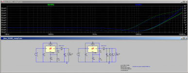
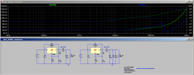
Just for completeness I have just added them with complete guesses for ESR. 10uF with 0.001 ohms ESR and 30nH ESL, 100nF with 0.001 ESR and 10nH ESL It makes very little difference at all in the audio band, so for the purposes of what I was showing I think it is close enough to say that the omission was not an issue, especially since jbau only showed data from 100Hz to 20Khz.
You may be interested to see what effect those extra caps have on the impedance at higher frequencies (again the ESR data for those extra caps was made up and is not really valid) in all cases green is with 560uF cap only and blue is with additional 10uF film and 100nf.
I've now also done some sims with the LT3080 (which is not a three pin so irrelevant to original purpose in this thread, of modifying existing PS) and I will be pursuing that, as it appears to be much better, and also simpler (though from the datasheet there are some layout considerations that are not necessary with the older three terminal regs)
Tony.
I need to look up the formulas for doing those types of calculations. It is easy to go into over engineering mode when you don't know what is actually critical Bruce, post 382 was the original comparison. The sims correlated well with what jbau reported. I just added in the diekman mod to compare, as I was interested to see if it made any difference, which it did.
Post 387 was done purely to show the effects of ESR in the output cap on the LM317 and was not supposed to be representative of jbau's circuit at all (jbau abandoned use of the LM317 completely by that stage). with the 20m Ohm in circuit the resonance is not removed it is just masked, hence taking the resistance out to better show the presence of the resonance.
With respect to the original comparison in post 182, I didn't put in the 10uF film and 100nf simply because I did not have esr data for them (jbau did give esr details for the 560uF cap), and I did not think that they would be relevant in the audio band. Putting in wildly wrong ESR data for these caps could potentially give misleading results.
Just for completeness I have just added them with complete guesses for ESR. 10uF with 0.001 ohms ESR and 30nH ESL, 100nF with 0.001 ESR and 10nH ESL It makes very little difference at all in the audio band, so for the purposes of what I was showing I think it is close enough to say that the omission was not an issue, especially since jbau only showed data from 100Hz to 20Khz.
You may be interested to see what effect those extra caps have on the impedance at higher frequencies (again the ESR data for those extra caps was made up and is not really valid) in all cases green is with 560uF cap only and blue is with additional 10uF film and 100nf.
I've now also done some sims with the LT3080 (which is not a three pin so irrelevant to original purpose in this thread, of modifying existing PS) and I will be pursuing that, as it appears to be much better, and also simpler (though from the datasheet there are some layout considerations that are not necessary with the older three terminal regs)
Tony.
Attachments
Last edited:
The ESR (or added resistance) should be in series with main output capacitor, not in series with regulator output. That RC acts as a snubber that loads the output resistively at crossover freqeuency for stability. Adding other output capacitors of smaller value is OK, mostly as local decoupling. The method to get this right is to plot open loop response of the regulator. The adjust capacitor forces maximum gain if big enough, so it does not complicate simulation, the stability calculation is the same for all Cadj above a few uF.
- Status
- This old topic is closed. If you want to reopen this topic, contact a moderator using the "Report Post" button.
- Home
- Amplifiers
- Power Supplies
- Another look at the LM317 and LM337 regulators