Anti-deadtime converter
Well, I think I may have finally outdone the Berning converter.
But I had to break a few design rules to do it.
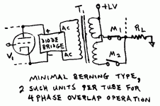
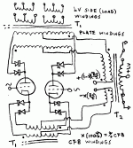
First, I have attached the most minimal Berning converter diagram for reference. This uses center tapped LV windings to reduce the # of Mosfets. It requires (as usual)) some dead time between opposite phases to avoid cross conduction, although this is not so severe as the H bridge / 4 Mosfet driver version. Snubbers on the Mosfets are mandatory here.
For low EMI generation, one uses two of these units per tube, operating 90 degrees out of phase with slowed switching transitions. The conduction overlap with 4 phases eliminates the dead time in the conversion process. So eliminating, in theory, any clock frequency in the audio and so no low pass fillter is required in the output path.
Don
Attachments
The Cuckoo converter!
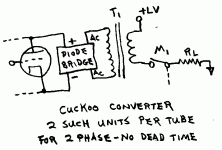
I have christened the new design as the "Cuckoo converter" since it likely will lead to that conclusion anyway. It breaks a few rules to say the least.
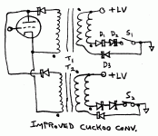
1st of all, it uses "anti dead-time" switching to eliminate dead time gaps in conversion with just 0 and 180 degree 2 phase switching. So call it the "anti dead-time converter" if you must have a technical name for the new design.
This is done by using either a no dead time or a slightly assymetrical 50+% duty cycle on each Mosfet (anti-deadtime). Cross-conduction is avoided by using only one Mosfet per xfmr. This means some air gap will likely be needed in the cores, but only a very small one, since we are not trying to charge any inductors up with current here, just avoid saturation.
Turn-on and turn off can be slowed some to avoid EMI generation, but not too much, since the magnetizing current must be accounted for as tube idling current. The Mosfets full-on duty cycles must still fulfill the 50% or 50+% criteria.
As hinted, the magnetizing current will be larger than with a no gap core design, so we will have to take it into account as a minimum idle current spec for the tubes. Fortunately the ramp-up of magnetizing current during one Mosfet's-On time is complemented by the other units ramp down of magnetizing current during it's Mosfet-Off time, giving smooth idle current (sets minimum idle current, we can still bias the tube higher).
Now for some accounting:
We have achieved the same results as the 4 phase Berning approach, but using only two Mosfets per tube. (the real Berning design, I believe, is still using H bridges, so has 8 Mosfets per tube in the 4 phase edition.)
The Mosfets can all be floating ground referenced for easy direct gate drives. (floating ground via a floating Cmos chip controller.)
The controller here is just 2 phases, so one CMOS F-F chip and an oscillator chip for a controller.
Number of xfmrs and total windings remains the same as the Berning.
How it performs, I don't know. For one thing, putting in air gaps in the cores without a resonating cap is going to increase leakage inductance. This can be minimized some by using a larger core, keeping the windings away from the air gap, and using the lowest switching frequency above the audio band practical. (we have to pay attention to any additional feedback bandwidth required though, the switching has to be faster or we get aliasing in the feedback)
Don
edit: Might be workable to put a CCS from the LV winding/Mosfet connection point to a higher LV++ to discharge the avg. magnetizing current during Mosfet off time. During Mosfet On time, the opposite tube converter's CCS would be cancelling it through the common load connection.
Attachments
Switchless Switchmode Converter
I believe I have cracked the problem wide open finally. This is an extension of an old idea I worked on some time ago for synchronous rectification on the low voltage side of a Berning like converter. I hadn't thought of applying it to the HV side too until today. And its a beautiful fit.
The most obvious deficiency of the Berning type (or SCIC too) converters is that a separate converter is needed for each output tube when there is really only one signal to be transferred.
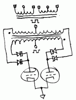
If we label the plate voltages for a P-P stage as A and B, we would really like to convey A-B then -A+B on alternating phases of the HF xfmr. So attached is just that.
The square wave signals shown on the HV center taps could be provided by some switching Mosfets to a B+ supply, or from a master switching xfmr (MSX) operated by two Mosfets on a LV primary winding. (The high voltage winding would be ground referenced to the tube ground.) The MSX approach will prove to be economical when dealing with the LV synchronous rectification side in the next post, since we can put another secondary winding on it. Notice that there are only commutating diodes in the HV conversion path, no switches.
Don
Attachments
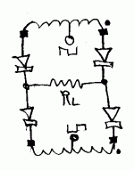
Now for the Low Voltage or Load side. We need to synchronously rectify the reduced impedance copy (LV xfmr. side) of A-B and -A+B (HF alternating from the conv. xfrmr.) plate voltages to the load. This could be done using a bunch of Mosfets in bridge configuration (the usual conventional way), but keeping with the switchless switchmode converter (SSC) theme, I will continue here to avoid any "switches" in the audio path. The attached diagram shows how this is done. the center tapped windings are the LV windings from the converter xfmr. carrying the A-B and -A+B signal. We just need to demodulate this from the HF "switching".
The center tapped squarewave control signals shown would be provided by Mosfet switches using a very low voltage secondary winding off the Master Switching Xfmr (MSX) for drain supply. The two center tap points just need two diode voltage drops across them to connect up the diode pathes (with enough current conduction to exceed the max audio signal). When disconnected though, they need a high impedance block, so the Mosfet off state provides this. Schottky diodes would be de rigueur here for the LV side commutation.
The opposite conversion/sync. rect. phase would be provided by two more LV conv. xfmr. windings with reversed phase and a similar center tap drive scheme using 180 degree controlled connect up phasing.
[I'm sure some other sync. rectification ideas can be dreamed up here as well. I'm looking soon at some way to "multiplex" the A-B ... signals back to (+ power supply - (A-B)) and (- power supply -(B-A)) form so that the simple two Mosfets to the + and - LV rails demultiplexing used in the Berning can be applied.]
A second copy of the whole shebang could be provided to operate 90 degrees out of phase for elimination of dead time in the conversion process (just like the 4 phase extended Berning scheme). And reduced "switching" slew rates then used to eliminate EMI generation from the HF.
Obviously, this design has no similarity at all to the Berning design.
There probably is some switched capacitor version as well, I'll have to work on that one yet.
Don
Attachments
What the smoke???
I believe your latest may be some sort of balanced mixer...
Dreamed up by the evilest sort of unbalanced mind. (as
usual, only in a good way) The next logical step is the
Magnetron from your old oven through a Magic T mixer.
Same exact circuit except for the leaking death ray...
Yet I am not sure that generating square waves of B+B-
amplitude to abuse diodes in a ring is going to allow for
fewer parts, or less lossy than straightforward chopping.
And I was only kidding about the oven. Probably...
--------------------------------------------------------------------
Your Cukoo tends to saturate when the tube does not
conduct. If anything else serves to reset that coil, then
it would also pull the audio output toward one rail. It
would be hard to avoid a buildup to destruction.
The magnetic circuit really needs to be driven equally in
both directions regardless of the tube's conductivity to
keep the magnetic circuit happy.... That the audio need
see as much as possible the tube alone in the common
mode.
---------------------------------------------------------------------
What absurdity of synchronus rectification comes next?
Time division multiplexing Left, Right, and Sub though
the same amplifier? If we are going off the deep end...
Re: What the smoke???
Clearly he likes it...
I like it also. It has a sort of brutal elegance to it. Still a current mode forward converter but uniquely balanced. This is relatively easy to drive, though I would say the B+ switcher and output rectifier drive are technically in the audio path and not trivial.
I'm not afraid of the B+ chopper. Just need to remember that going beyond about 200V/uSEC starts eating switching power. I would look at half bridge drives to get symmetric switching.
I think the 4 phase approach may be the best solution. So it would take 4 half bridge B+ choppers (8 MOSFETS) on the high side and the same on the low side for the rectifier drive. 16 MOSFETS all driven from a quadrature clock driver switching 4 B+ windings and 4 low side windings. Also 8 HV fast/soft diodes plus 8 LV fast recovery diodes.
100 KHz might be a good frequency because the core losses and HV switching are quite a bit more manageable. Looking at core materials and allowable Bmax etc. I think the secondary could be done in fewer sections as fewer turns are needed at higher Bmax in the core.
Also could use a u-core or similar geometry that allows the winding to be sectioned easily, even though the path is longer. You can just put bobbins in series and also isolate the high side from the low side.
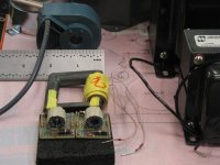
(The big core in the photo is a U core for a 100 KHz 400 watt converter with +/-200V full bridge phase modulated drive and a 20KV secondary.)
That's my take on it anyway. I think this is the closest to practical I've seen so far and may be ultimately more practical than some of the other schemes.
Michael
kenpeter said:I believe your latest may be some sort of balanced mixer...
Dreamed up by the evilest sort of unbalanced mind. (as
usual, only in a good way) (...)
Clearly he likes it...
I like it also. It has a sort of brutal elegance to it. Still a current mode forward converter but uniquely balanced. This is relatively easy to drive, though I would say the B+ switcher and output rectifier drive are technically in the audio path and not trivial.
I'm not afraid of the B+ chopper. Just need to remember that going beyond about 200V/uSEC starts eating switching power. I would look at half bridge drives to get symmetric switching.
I think the 4 phase approach may be the best solution. So it would take 4 half bridge B+ choppers (8 MOSFETS) on the high side and the same on the low side for the rectifier drive. 16 MOSFETS all driven from a quadrature clock driver switching 4 B+ windings and 4 low side windings. Also 8 HV fast/soft diodes plus 8 LV fast recovery diodes.
100 KHz might be a good frequency because the core losses and HV switching are quite a bit more manageable. Looking at core materials and allowable Bmax etc. I think the secondary could be done in fewer sections as fewer turns are needed at higher Bmax in the core.
Also could use a u-core or similar geometry that allows the winding to be sectioned easily, even though the path is longer. You can just put bobbins in series and also isolate the high side from the low side.
(The big core in the photo is a U core for a 100 KHz 400 watt converter with +/-200V full bridge phase modulated drive and a 20KV secondary.)
That's my take on it anyway. I think this is the closest to practical I've seen so far and may be ultimately more practical than some of the other schemes.
Michael
Attachments
"Your Cukoo tends to saturate when the tube does not
conduct. If anything else serves to reset that coil, then
it would also pull the audio output toward one rail. It
would be hard to avoid a buildup to destruction."
Yep, I agree the core flux does need balancing there (for the Cuckoo). The CCS core balancing might be workable if it is servo'd so as to balance the current precisely. It shouldn't build up in the audio though as I see it, because the CCS for one tube side pulls to the +LV rail and the other tube side CCS pulls toward the -LV rail. So they cancel during the time they are both connected together to the load. During the disconnect time is when they would have to null out the accumulated core fluxes. But any mistracking between them would show up in the audio. The details might be killers here. So I will relegate the Cuckoo conv. to the DoDo bin for now in light of the more interesting SSC option now.
------------------------------
On the SSC version, the B+ switcher drives and the output rectifier drives can all be generated by one control xfmr driven by LV Mosfets (well per 2 phases).
Also, the B+ switching is requiring a lot less severe voltage swing than in the Berning case, since that has to handle peak B+ to minus peak B+ swing.
This only has to handle avg. B+ to 0 swing, which can be formed from DC (B+avg)/2 and +/- (B+avg)/2 swing (ie, nearly a 1/4 of the Berning swing). Going to 4 phase will greatly relax the required voltage slew rates as well (we'll actually want to slow them down then).
What's interesting about the diode bridge demod scheme is that the voltage drops on opposite (ends of winding) pairs of diodes cancel each other to 1st order (ie, no effect on signal), but the Vdrops do differ some due to current differences from the audio.
The LV side cross conduction demod control currents can be pushed to arbitrarily high current levels so as to greatly mimimize the effect of the audio current on the Vdrops. (this same cross diode conduction scheme could be applied to the HV side as well, but I think it is an unnecessary complication there.)
There is nothing going on here at all like a conventional diode mixer which depends on non-equal diode drops for non-linear effects, this is just ordinary multiplexing by switching (somewhat in disguise however). (really just the old sampling diode switch from days of yore, but updated with some big honker diodes)
One could just use a conventional Mosfet bridge demod instead, but it ends up having diodes in series with the Mosfets anyway to block the reverse conducting diode in the Mosfet. And those diodes only have audio current, no swamping out control currents.
"Switchless" seems like it might be a little more "cachet" for promo purposes. You know.... Berning has switches in the audio path, we don't. hehe

Don
conduct. If anything else serves to reset that coil, then
it would also pull the audio output toward one rail. It
would be hard to avoid a buildup to destruction."
Yep, I agree the core flux does need balancing there (for the Cuckoo). The CCS core balancing might be workable if it is servo'd so as to balance the current precisely. It shouldn't build up in the audio though as I see it, because the CCS for one tube side pulls to the +LV rail and the other tube side CCS pulls toward the -LV rail. So they cancel during the time they are both connected together to the load. During the disconnect time is when they would have to null out the accumulated core fluxes. But any mistracking between them would show up in the audio. The details might be killers here. So I will relegate the Cuckoo conv. to the DoDo bin for now in light of the more interesting SSC option now.
------------------------------
On the SSC version, the B+ switcher drives and the output rectifier drives can all be generated by one control xfmr driven by LV Mosfets (well per 2 phases).
Also, the B+ switching is requiring a lot less severe voltage swing than in the Berning case, since that has to handle peak B+ to minus peak B+ swing.
This only has to handle avg. B+ to 0 swing, which can be formed from DC (B+avg)/2 and +/- (B+avg)/2 swing (ie, nearly a 1/4 of the Berning swing). Going to 4 phase will greatly relax the required voltage slew rates as well (we'll actually want to slow them down then).
What's interesting about the diode bridge demod scheme is that the voltage drops on opposite (ends of winding) pairs of diodes cancel each other to 1st order (ie, no effect on signal), but the Vdrops do differ some due to current differences from the audio.
The LV side cross conduction demod control currents can be pushed to arbitrarily high current levels so as to greatly mimimize the effect of the audio current on the Vdrops. (this same cross diode conduction scheme could be applied to the HV side as well, but I think it is an unnecessary complication there.)
There is nothing going on here at all like a conventional diode mixer which depends on non-equal diode drops for non-linear effects, this is just ordinary multiplexing by switching (somewhat in disguise however). (really just the old sampling diode switch from days of yore, but updated with some big honker diodes)
One could just use a conventional Mosfet bridge demod instead, but it ends up having diodes in series with the Mosfets anyway to block the reverse conducting diode in the Mosfet. And those diodes only have audio current, no swamping out control currents.
"Switchless" seems like it might be a little more "cachet" for promo purposes. You know.... Berning has switches in the audio path, we don't. hehe
Don
Wake up and smell the diode
Where do you get the idea that you won't have to switch B+/B- ?
Nevermind that you drive from balanced nodes; You still have to
overwhelm B+/B- voltages at the far corners of the bridge for it
to open(and close) the correct paths.
Are you switching one to ground and leaving the other open?
Still at the very least B+ you will see on the open switch and
open diodes... Where is the safety path for ringing opposite to
the bridge to conduct?
"Where do you get the idea that you won't have to switch B+/B- ?"
Not sure if I follow you on this.
The tube plates never go negative. Think of each center tapped HV winding as a conventional P-P OT. We just raise the B+ to get it working thru the tubes. Then we drop that B+ and raise the other one on the inverted phase winding. Sorta like taking snapshots of a normal P-P operation, except we keep swapping the phase of the winding by the B+ power up multiplexing. So the center taps just swing from 0 to B+ and back. (and can get that by DC B+/2 and +/- (B+/2) swing.)
Worst case analysis:
Lets say the tubes are swinging from 10V to 190V with a 100V B+. So the winding with 100V B+ on it will be operating mormally, with 10V on one end, 100V at the center, and 190V at the high end. The other winding will have the center tap at 0V, neither the 10V plate or the 190V plate will be able to conduct thru its diodes to that winding.
Maybe you are confusing the HV side operation with the LV side operation, which does use cross conduction thru the (same side) diodes. No cross conduction here. It --could-- be added to null out the diode drops as on the LV side, but would require two more center tapped HV windings to do it. But since the tube conduction is unidirectional anyway (not bipolar like the LV load output side), the diode drop voltages occur in both plate current pathes, nulling out to 1st order anyway. Almost the same as just lowering the B+ by one diode drop.
On the LV side, with the diode cross conduction method, there ARE Mosfet switches controlling the application of the cross conduction pulses (+/- 2 diode drop voltage deltas) to the center taps.
Thats because the audio current could flow around the diodes and thru the centertaps between top and bottom windings without the switch blocking it. (these LV bottom windings are missing in the HV multiplexing case since we don't have bidirectional current flows on the HV side)
Don
OH, on the Cuckoo converter, without the flux cancellation option added, it is just using two air gapped SE OT xfmrs and switching phase between them as it multiplexes back and forth. Thats why I called it the cuckoo converter, since we were originally trying to get rid of air gapped SE xfmrs. It's just a Berning implemented with SE HF xfmrs.
Putting in the flux cancellation scheme using controlled CCSs would allow it to return to non-air gapped xfmrs. But its a little too close to the Berning still for comfort, patent-wise.
On the other hand, the latest SSC is actually outperforming the Berning in an important way. It can be configured to do CFB (cathode feedback) without the troublesome % of HV derived from the LV supply showing up in the cathode winding.
Here is the CFB version of the SSC. 100 X = % CFB
The +(1-X)(B+/2) and -X(B+/2) voltages can be shifted around to suit the tube grid biasing, they just need to sum to B+/2 and set the ground reference correctly for the grid.
OH, and one more advantage for the SSC is the need for only one LV supply. (But then it does need a HV supply. Actually just B+/2, the bias offset reference part is the usual low current one. Ie, there is B+/2 between the two T2 winding terminals, then a low current bias supply sets the ground reference for that) The 2 diode drop+ commutation AC voltages would also come off addional T2 secondary windings.
Don
Attachments
Here is a comparison of various DC/DC converter technologies, maybe there´s some useful information for you:
http://focus.ti.com/lit/ml/slup117/slup117.pdf
http://focus.ti.com/lit/ml/slup117/slup117.pdf
"Here is a comparison of various DC/DC converter technologies, maybe there´s some useful information for you: ....."
Yes, thanks! I found something useful there too, a fix for the Cuckoo converter flux reset:
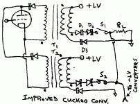
The standard Forward converter topology uses a second primary winding and a diode to discharge the accumulated core flux from the Mosfet ON period, during the Mosfet OFF period. Normally this requires that the ON period be less than the OFF period by some margin. Since we want to reverse that duty ratio to gain overlapping ON cycles (the anti dead-time thing) for the two converter stages powering one tube, we will have to carefully break the rules again.
By operating the ON cycle at reduced voltage versus the OFF cycle, we can speed up the flux discharge. So you will notice some series diodes in the Mosfet current path to drop the LV+ supply a little.
This will allow us to exceed 50% ON duty by a tiny amount, which is all we need to get the overlapping converter phases from the two xfmrs. powering the tube.
The controller can be made using just a CMOS F-F IC for 50/50 %duty and then an RC network to delay turn off time a tiny bit. (Usually its got to be the other way, delaying the turn on time to get dead time for safety)
Also notice that the rectification for the tube has been reduced to a single diode on each xfmr. This is so the slightly increased voltage appearing at times during core reset will not affect the tube operation from the other ON cycle phased xfmr.
This is a darn simple converter now. It's back on the map again I think. One drawback would be the non-linear effects of the series dropping diodes on the LV side, I guess we could put a big cap across them.
Don
OOPPPs! Just noticed that the diagram is missing the load resistor(speaker). Fixup: The Mosfet current path would be in series with the load, the flux reset diode path would be connected to ground (skipping the load). The two phase xfmr/Mosfet assemblies shown power one polarity of the output, and another similar pair (likely using P-channel Mosfets instead of the N channel ones for simple gate control ) would be connected to a - LV supply for the opposite polarity load output.
----------------------------------
I'm also taking another look at the Cuk converter scheme too, seems that with the coupled inductors it does NOT have any inductance flapping space remaining (its constrained by xfmr action)) to wreck voltage regulation (although there will still be some leakage inductance causing some deterioration).
The double boost converter or other simple inductor converters (Buk...) are still unsatisfactory due to their un-constrained series inductance.
---------------------------------------
OH, and a big Wuuppps, to fix up on the SSC comments above. It turns out that it DOES put %CFB * (LV+)/2 DC into the CFB winding, similar to the Berning design (half as much as the Berning, but we still have to take the same remedial actions to compensate the tube grid biasing in either case for CFB designs).
So there is NO real advantage for the SSC versus the Berning design for CFB (cathode feedback) designs.
Attachments
Time for some accounting:
The Cuckoo converter is performing overlapped conversion (equivalent to 4 phase) using 4 Mosfets and 4 xfmrs. The Mosfets are all easy ground referenced gate drives. Just need a CMOS F-F and an Osc. chip for a controller.
The SSC (switchless switchmode conv.) is performing 4 phase overlapped conversion using 12 Mosfets, and 4 xfmrs. The Mosfets are all easy ground referenced gate drives. Takes 4 CMOS ICs for the controller and an Osc. chip.
The SCIC (switched capacitor impedance conv.) is using 8 Mosfets and 4 air gapped inductor/xfmrs (and quite a few diodes and caps.) for 4 phase overlapped conversion. The Mosfets are all easy ground referenced gate drives. Takes 4 CMOS ICs for the controller and an Osc. chip.
The Berning (4 phase Quadrature edition) is using (I believe) 16 Mosfets (due to H bridges, could be simplified to 8) and 4 xfmrs. At least half the Mosfets require floating drives (due to H bridges). Looks like it might be using a discrete part controller. (but could be implemented with 4 CMOS ICs and an Osc. chip if not using the H bridges.)
The plain vanilla Cuk converter requires 4 Mosfets and 4 xfmrs (2 of which are air gapped coupled inductors) for the fixed impedance ratio version. All Mosfets are easy ground referenced gate drive. Just needs a CMOS F-F and an Osc. chip for the controller.
The variable impedance ratio Cuk converter requires 4 Mosfets and 4 xfmrs. (2 of which are air gapped coupled inductors) All Mosfets are easy ground referenced gate drives. Requires one PWM controller chip and a pot. with a knob for adjusting the impedance ratio.
All above versions put DC into any CFB winding, making them a nuisance to bias the tubes steadily for CFB.
Don
It would seem the Cuk converter is the leading economic contender here. It is untried, and likely has a lower intrinsic damping factor than the others without feedback. I believe it also will have some phase shift concerns as far as global feedback are concerned (it has been used in class D amplifiers with success however, so phase is tame-able, going to higher freq. switching improves this within the audio range too of course)
Its inductor/xfmr design is rather more complicated than the others too. (Its infrequently used commercially for this reason. Plus it was patent protected for some time, but not any more.)
(it has a right half plane, non-minimum phase zero in its response, which usually spells trouble for feedback stability. But this is correctable (becomes a a left half plane zero, minimum phase response) with inclusion of a practical amount of winding resistance in its two inductors. It then has very desirable single pole slope at the 0 db gain crossover. This is in contrast to ordinary output xfmrs which have nasty two pole slope at HF. The mimimum winding resistance will however lower intrinsic open loop damping factor further)
-------------------------------------------
The Cuckoo converter is looking good for its parts minimum and likely is working without phase issues. The question here would be whether it is sufficiantly different from the Berning design to avoid patent issues. Clearly the Berning design doesn't use its novel anti-dead time scheme. And the Cuckoo is using a forward converter topology instead of a P-P conv. topology. So maybe OK?
-----------------------------------------------
Finally I will note that the SSC conv. can be modified to use a sorta Berning like (but at this point proprietary) Mosfet demultiplexing scheme on the LV side, (instead of the cross conduction diode bridge scheme). The total number of Mosfets for either scheme is 8, for a 4 phase version. (I incorrectly have 12 Mosfets listed in the previous post for the SSC, should be 8)
So no big deal. I will refer to this version as the Matrix converter. The capabilities, overall topology, and the new HV side configuration of the Matrix and SSC converters are identical other wise.
Don
Gee, I just realized that the SSC/Matrix designs could be operated with the anti dead-time forward conv. topology too, just like the Cuckoo derived from the Berning. This cuts the number of Mosfets there down to 4 now, I think. Back in the economy race again.
I'll stop inventing impedance converters now. Looks like we have enough. Went from no way to get around the Berning, to too many ways to decide!
Don
I'll stop inventing impedance converters now. Looks like we have enough. Went from no way to get around the Berning, to too many ways to decide!
Don
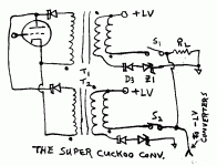
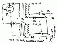
The Super Cuckoo converter
Here is a nice improvement on the Cuckoo impedance converter.
Instead of dropping the forward voltage, I just increased the flux reset voltage with a zener, Z1. This gets rid of the non-linear diodes out of the audio path, so no cap around the diodes needed. The zener, Z1, could be a 6.3V one to generate some filament power even.
The Mosfet(s) could be moved around to the LV rails too, if that seems easier to drive.
(I'm planning on using a floating CMOS controller, floats on the audio level, uses a double bobbin 60Hz power xfmr. for low common mode capacitance,20 pF, to the power line to power it. But putting the Mosfets at the LV rails would eliminate even that tiny bit.)
As before, it runs with two overlapping phases per conv., and a converter for each tube, yielding 4 xfmrs (no air gaps), and 4 Mosfets ( with easy direct gate drives).
I think this definately puts the Cuckoo as the heavy weight contender now for simplest/easiest converter.
Don
Attachments
The Uni_Cornverter
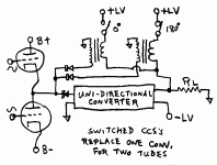
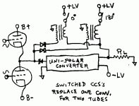
I finally figured out how to do the switched CCS's scheme to get rid of one converter properly. The CCS's operate in Flyback mode, with two phases to get almost ripple free current. (it would take 4 phases to get true ripple free current, but since we are subtracting the same thing out on the LV side, it doesn't have to be perfect)
The bipolar output of the totem pole tubes is converted to uni-polar output with the addition of the switched CCS current. The unipolar converter can be a Berning type, a Cuckoo type, a SCIC, or a Cuk type impedance converter.
On the other LV end, the CCS current is subtracted out again, via the CCS primaries, to return to bipolar current output mode to drive the speaker.
Ohh, the diagram really should say uni-polar converter, not uni-directional converter.
Obviously, this is a niche application. Not many totem pole designs around.
I'm still a little curious if this couldn't be expanded to a full switched CCS converter somehow by doubling up the CCS's and deleting the converter. But no breakthru yet.
Don
Arrgh..., just noticed that the diodes are backwards in the diagram on the CCS to tube connection.
Attachments
Geeee, big Duhhh on the Super Cuckoo:
We don't need the zener diode, just decrease the number of turns on the diode/flyback winding a little bit (maybe 10%) with respect to the Mosfet driven winding. That will make the flux reset go faster than the flux buildup, allowing the ON time to be greater than the OFF time. Energy efficient too.
Arrgh: I know, the diagram is showing more turns, not less. Needs fixing again.
Don
Attachments
- Status
- This old topic is closed. If you want to reopen this topic, contact a moderator using the "Report Post" button.
- Home
- Amplifiers
- Tubes / Valves
- Another kind of hybrid
