Roasting the sacred cow
Was actually thinking of replacing the OP-FET arrangement
in one or both current mirrors with TI's new heatsinkless
Class-D chips. As long as its slave to whatever the Triode's
RSense tells it to do... And the tube participates in driving
the real load.
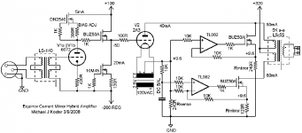
Its not a simple transfer function fn(vGrid)=rPlate, but a
three terminal fn(vGrid,vPlate)=rPlate, involving all the
dynamics the OPT, power supply, and loudspeaker may
react upon vPlate.
One has to be very careful not to dumb it down and isolate
the tube from the load, or its just a fancy pile of sand. I think
everyone posted here in this thread already understands
this, but I still wanted to make written record of the point....
We may be cheating, but carefully cheating only the right
things. Perhaps even the OPT could go... Yet even with
OPT, no reason any mirrors must work exclusively upon
the high impedance side.
One might still want the Tube B+ to sag (for reference),
even if assisted by regulated low impedance B+ through
the slaved mirrors.
If everything sand does only what the tube tells it to do,
we must still make sure the reference tube sees nothing
abnormal in the load that might make it act un-tubey....
Was actually thinking of replacing the OP-FET arrangement
in one or both current mirrors with TI's new heatsinkless
Class-D chips. As long as its slave to whatever the Triode's
RSense tells it to do... And the tube participates in driving
the real load.
Its not a simple transfer function fn(vGrid)=rPlate, but a
three terminal fn(vGrid,vPlate)=rPlate, involving all the
dynamics the OPT, power supply, and loudspeaker may
react upon vPlate.
One has to be very careful not to dumb it down and isolate
the tube from the load, or its just a fancy pile of sand. I think
everyone posted here in this thread already understands
this, but I still wanted to make written record of the point....
We may be cheating, but carefully cheating only the right
things. Perhaps even the OPT could go... Yet even with
OPT, no reason any mirrors must work exclusively upon
the high impedance side.
One might still want the Tube B+ to sag (for reference),
even if assisted by regulated low impedance B+ through
the slaved mirrors.
If everything sand does only what the tube tells it to do,
we must still make sure the reference tube sees nothing
abnormal in the load that might make it act un-tubey....
I agree that there are a few experimenters that are not afraid to try something new. Many of them can be found on this forum. If no one tries anything new we will all be building the same amps that have already been published. Not that I have anything against that, but after 40 years of amp building, I have already done enough of that. I have experimented with a lot of whacky ideas, some worked, some showed signs of hope, some didn't work, and some just blew up. I have posted some of the better ideas on my web site, and discussed a few on this forum, where they seem welcome (unlike some other forums).
OK, here is one of my ideas that sort of worked. It blew up a lot, and got no interest, so I put it aside a few years ago. I may try it again some time.
http://www.tubelab.com/SSopt.htm
I acquired a pair of 50 pound chokes (3 HY, 2 Amps, 5 ohms) for a SE OTL experiment. I haven't had the time to try it yet though. Maybe tube - transistor cathode follower "darlington" design. I tend to make these things up as I go, and quit when it works, or the pile of fried parts gets too big.
I experimented with a solid state "current booster" on the output side of the OPT. It was one of those experiments that I didn't talk about. This doesn't mean that it isn't a good idea, only that I didn't know how to do it!
Again, this experiment occurred several years ago. The mosfets that I used were already a few years old and have a lot of gate capacitance. I have learned a lot in the years since, and I wouldn't base any component decisions on those old experiments. The BJT has a SOA limitation that mosfets do not generally have. I blew up a few transistors before I found the MJW21195. It is the only one that could (at the time) handle 250 volts and 200 mA simultaneously. It is important in the "darlington" circuit that I used that the device have a relatively constant beta over the current range being used.
We may be cheating, but carefully cheating only the right things. Perhaps even the OPT could go...
OK, here is one of my ideas that sort of worked. It blew up a lot, and got no interest, so I put it aside a few years ago. I may try it again some time.
http://www.tubelab.com/SSopt.htm
I acquired a pair of 50 pound chokes (3 HY, 2 Amps, 5 ohms) for a SE OTL experiment. I haven't had the time to try it yet though. Maybe tube - transistor cathode follower "darlington" design. I tend to make these things up as I go, and quit when it works, or the pile of fried parts gets too big.
Yet even with OPT, no reason any mirrors must work exclusively upon the high impedance side.
I experimented with a solid state "current booster" on the output side of the OPT. It was one of those experiments that I didn't talk about. This doesn't mean that it isn't a good idea, only that I didn't know how to do it!
Interesting that you found BJTs sounded better. That will be worth a test in my topology.
Again, this experiment occurred several years ago. The mosfets that I used were already a few years old and have a lot of gate capacitance. I have learned a lot in the years since, and I wouldn't base any component decisions on those old experiments. The BJT has a SOA limitation that mosfets do not generally have. I blew up a few transistors before I found the MJW21195. It is the only one that could (at the time) handle 250 volts and 200 mA simultaneously. It is important in the "darlington" circuit that I used that the device have a relatively constant beta over the current range being used.
I'm with you on the tube having to experience the load for good emulation or augmentation. Also helps to keep everything in Class A operation, getting into Class B mode brings up some concerns about crossover effects and tracking between tubes and un-tubes. Although, there have been schemes that run the tubes class A and bring in pentode or SS assist at class C levels for high output.
I've thought about putting the SS current assist on the secondary side of the xfmr too. The circlotron (or a totem pole output stage) works well for putting bipolar darlingtons in the cathodes to current drive the secondary. Sziklai bipolar add-ons for tubes waste too much power. Likely to get stability problems unfortunately in any case with the xfmr phase shift in the local loops.
There is a very fancy composite amplifier way to put current assist on the secondary. Basically uses a SS current output amplifier that parallels the tube output with a current sense resistor in the speaker return lead between the tube amp and the SS amp gnd returns. The SS current amp tries to zero out the return current to the tube amp, effectively unloading it. The tube amp sets the voltage still. Requires two complete amplifiers, so expensive. And may have some stability issues to deal with using real speaker loads.
One could play with the endless possibilities forever. (take a look at the Class G/Class H thread by Dhaen I think too for more SS assist ideas. The class D amp would be useful for providing voltage rails for the tube amp.)
Don
I'm not afraid to try something new, but I think the next step for me is scaling this idea up a little and using a linear tube. I want to explore the sonic potential of this in a practical HiFi amp.
How about 16 watts from a SE 2A3 with a damping factor of >6 ? With 4X current boost the 2A3 can play into a 5K load for a very linear load line. The "anode" efficiency is about 30% in this case; 16 watts Po from 52 watts B+.
This is something I already have the parts for. I thought I would add another piece of sand or 3 to the driver as well after perusing the tubelab.com site.
Using a MOSFET voltage follower allows me to build a 2 stage amp with more gain and linearity in the first stage, and use what I consider to be a great sounding tube, while providing good drive to the output tube.
Actually I guess it's a 3 stage amp if you count current gain as a stage... Anyway I was thinking of a DC choke coupled design and decided to give DC + MOSFET coupling a try.
This way if I get a loose socket pin in the driver I blow up not only the 2A3 but a couple of $10 MOSFETS also. I will use a fuse to protect my UTC iron, though.
Cheers,
Michael
Attachments
smoking-amp said:Although, there have been schemes that run the tubes class A and bring in pentode or SS assist at class C levels for high output.
I had several versions of amps called "Swinnik" (may be translated like "Piggie"), they worked exactly in A+C. Nice results, really nice.
Michael Koster said:I'm not afraid to try something new, but I think the next step for me is scaling this idea up a little and using a linear tube. I want to explore the sonic potential of this in a practical HiFi amp.
How about 16 watts from a SE 2A3 with a damping factor of >6 ? With 4X current boost the 2A3 can play into a 5K load for a very linear load line. The "anode" efficiency is about 30% in this case; 16 watts Po from 52 watts B+.
This is something I already have the parts for. I thought I would add another piece of sand or 3 to the driver as well after perusing the tubelab.com site.
Using a MOSFET voltage follower allows me to build a 2 stage amp with more gain and linearity in the first stage, and use what I consider to be a great sounding tube, while providing good drive to the output tube.
Actually I guess it's a 3 stage amp if you count current gain as a stage... Anyway I was thinking of a DC choke coupled design and decided to give DC + MOSFET coupling a try.
This way if I get a loose socket pin in the driver I blow up not only the 2A3 but a couple of $10 MOSFETS also. I will use a fuse to protect my UTC iron, though.
Cheers,
Michael
I like it. Though, tube non-linearities are "highlighted" such a way.
tubelab.com said:OK, here is one of my ideas that sort of worked. It blew up a lot, and got no interest, so I put it aside a few years ago. I may try it again some time.
http://www.tubelab.com/SSopt.htm
[/B]
Smokin had pointed me to another style that put the power
on the low voltage side with the loudspeaker load balanced
somehow inbetween two very small switching transformers.
One PP switchin tranny for Tube Push, One PP switchin tranny
for Tube Pull. And of course, four high current switching FETs.
And square wave of fixed 50% duty cycle.
The high V side don't need timed FETs to blow up. But just
used diode bridges, and each transformer has one tube on
the bridge that acts as a variable audio frequency load.
I don't have that link anymore, ask Smokin if he does.
There's a patent, but you can prolly think a dozen ways
to southern engineer around it. Piezo Transonars come
to mind...
That would be David Berning's switchmode OT, patent # 5,612,646 . Seems to me I saw this same scheme in EDN in the early 90's, but without the tube. Anybody recall this? Sure would like to find that circuit design note.
More recently I posted on the switched capacitor impedance converter:
http://www.diyaudio.com/forums/showthread.php?s=&threadid=116507&highlight=
It has performance similar to the Berning design. About 10X conventional xfmrs for 250KHz switching. (and it has far LOWER shunt capacitance across the tube than a conventional OT too, like 10X lower. I'm guessing the capacitance issue is why no one replied to the thread, but it comes out far lower Cshunt than a usual OT, not far higher)
These two schemes are replacements for the OT, not tube emulation or augmentation. But both are easily amenable to using SS to modulate the B+ rails for the tubes, and do all their switching on the LV side too.
But you don't really need such an exotic output xfmr to do low voltage SS modulation of the B+ rails:
http://www.diyaudio.com/forums/showthread.php?postid=1409048#post1409048
http://www.diyaudio.com/forums/showthread.php?postid=871030#post871030
It does however require an OT with a very low secondary Zout (not 8 Ohms).
Don
Here's a type of transparent booster on the secondary side. I believe it gives 2X power out compared to the tube output, since the voltage gets doubled. The tube amp sees 1/2 the voltage and 1X the current on the load thru a 2 Ohm output, so Zload is doubled effectively (ie, 4 Ohm load on 2 Ohm output).
Attachments
re: tubelab SSopt
Did the MOSFETS blow up one at a time or in pairs?
I guess this would run at 50/50 duty cycle as a switching impedance converter. No pwm or frequency control. A breeze to control, can focus more on the switching losses.
For the full bridge topology my favorite switching technique is phase modulation with zero voltage switching at each end of the primary. The idea is to release one end, then catch it with the other MOSFET just as the voltage across the MOSFET is zero. Then you switch the other end the same way and a new conduction cycle starts.
This tends to be most efficient and does not subject the MOSFETS to large overvoltage spikes if done properly. Needs no snubber network, just careful tuning of the primary inductance and MOSFET Coss. Sometimes a little tuning capacitor or inductor as in quasi-resonant but phase modulation can run at fixed frequency. It's possible to get outstanding efficiency.
Unfortunately, it's still easy to blow up FETS but it is possible to guess the switching toime well enough to succeed the first time.
I guess you have switching bridges on both sides to avoid the issues with passive rectifiers, as theoretically you only need a rectifier on one side. It would be an advantage to put the passive rectifier on the HV side since it would be least likely to introduce crossover distortion. However this means driving from the load side. It doesn't really matter from the transformer's point of view.
US Patent 5,612,646:
This drives the system from the load side. Nowhere does it seem to allow for a similar technique driven from the tube B+. Nor does he call attention to the advantages of driving from the load side. Driving from the tube side does not seem to be covered.
This is IMO a very narrow patent that only really covers the one circuit. Driving from the tube side would for example be a different invention. Using active rectification on the tube side if driven from the load would be a gray area. (NB I only spent about 5 minutes reading the patent)
It's nice to know that advantages include eliminating blocking distortion (good writeup on the subject actually), and preventing your amp from catching fire if you forget to connect a load.
Switched capacitor impedance converter:
Intriguing technique. I have built a multiplier like this but not a divider. The multiplier SMPS I built could be modulated by audio to make a "singing arc" but that's another story...
The multiplier would work in reverse as a divider. I'm still digesting this. Some of the better VM topologies for power conversion (parallel?) allow the capacitance to be progressively increased toward the LV end.
General:
Transformers for these applications should be dead simple and tiny. My full bridge switching converter used a transformer core less than one pound (way less I think) and was good for 400 watts. A 20-50 watt tube amp converter would not take much cross section at 200 KHz. I think I have some toroids. Imagine... cheap tiny ferrites... A whole converter for 50 watts could fit in a shirt pocket and weigh less than a pound, heatsinks and all. I guess you would want more for a bass amp...
All of this with the goal of delivering what Berning calls the subjective performance of tube amplifiers, having "no analog signal processing by solid state devices"...
However I wonder about the subjective contribution of core saturation, which would presumably either not occur or occur with different results in the switched converter designs. The musical performance of an amplifier is in part determined by it's response to transient overload conditions which occur normally in most music due to the 14-18db (or more) dynamic range above the VU meter's top reading. Of course, a lot of today's recorded music doesn't have this much dynamic range for other reasons but that's another rant..
Michael
Re: Michael
If you drive the HF converter from the tube side and use rectifiers on the LV side, you end up with a problem with unwanted diode conduction when the other polarity/tube/conv. tries to pull the output voltage the opposite polarity. At least on the tube side, the polarities are separate, so diodes are OK there.
For the switched capacitor imp. conv. (SCIC) scheme I am using graded capacitance values in the multiplier from the HV end to the LV end. (its mentioned in the post) This is how I was able to get the shunt capacitance across the tube so low. The capacitive reactance at the LV end is comparable to the load Z (at the switching freq.) for maximum charge transfer. The Xc at the tube end is N times higher.
Since a conventional OT has capacitance comparable to the reflected load Z at its top frequency limit (critically damped resonance), the ratio of relative shunt capacitance in the SCIC is reduced by the ratio of switching frequency to conventional xfmr resonant frequency. The Hammond xfmrs I have are resonant at about 35KHz.
The original Berning design uses 2 phase (0,180) switching per converter (ie., one xfmr per polarity/tube) and has to use fast switching rates to avoid dead time (other than minimal safety dead time) in the conversion (as the patent shows). To do this he uses pulse xfmr gate drives since the N channel mosfets are floating around at audio signal levels and he uses two half bridges per xfmr.
I had some time ago posted some thoughts on using 4 phases (two xfmrs, one 0 and 180, the other 90 and 270) in the Berning design so as to greatly relax the switching times needed due to the resulting overlap between phases. This eliminates or relaxes the need for a HF filter on the output, but mainly is useful to avoid generation of EMI for DIY applications by using slow slew switching. There was some (wishful?) speculation that he might come out with a converter kit or assembly for DIY. I see he has taken up the idea for a 4 phase converter now on his WWW site, called the Quadrature Z ($30K). Appears to still be using the half bridges and pulse xfmrs. Takes advantage of the doubled up converters to double the power output.
The 4 phase switching is almost mandatory with the resonant converters in the SCIC I posted in order to get ripple free conversion. And while 4 phases does double up the number of converters, there are some simplifications that can be made in the gate drives. Since the slew rate of the switches can be dropped with the 4 overlapping phases (so avoiding EMI), the gate drives do not need to be fast, in fact are purposely slowed down.
Instead of two half bridges, I went to a center tapped LV "primary" with N channel Mosfets for one output polarity and P channel outputs for the other (this cuts the number of Mosfets in half). They are all floating on the audio signal, but are gate drive referenced to the same point. By making the gate drives from a floating CMOS controller, they are easy to drive directly, so no pulse xfmrs. My whole controller is just 4 HCMOS chips.
This ends up with the same number of Mosfets as in the original 2 phase Berning design plus a greatly simplified controller. (although it may still be necessary to use bigger or doubled up P channel Mosfets to get the same Rds_on as the N channel ones. I'm leaving room for doubled P channels on the PC board just in case) Also, I do have to put RC snubbers on the Mosfets with the center tapped primary configuration, but they shouldn't have to dissipate any power with the controlled switching slew rates.
Another seemingly apparent concern with the SCIC is signal bandwidth. Looks like it couldn't be more than the switching frequency (Fs) divided by the number of multiplier stages (N). This turns out not to be the case (for 4 phase continuous conduction anyway). Bandwidth is Fs due to shunt capacitance and sampling limit. What does drop off at Fs/N is the audio signal slew rate. Fs/N is easy to get above the audio band, so slew rate is just applying to tiny feedback error signals, so not a problem at all.
A HF band limit also crops up in the Berning design due to the leakage inductance in the ferrite xfmrs. It is stressed at the full switching frequency directly. The resonant SCIC on the other hand nulls that out with the resonant Xc.
So it seems likely that the two are comparable in bandwidth. Neither suffers from hysteresis. Both work down to DC. Both can be made EMI quiet. Parts cost about $50 for either one.
Don
Did the MOSFETS blow up one at a time or in pairs?
They blew up in pairs, or every once in a while all 4 would fry! I don't claim to be an expert in SMPS. I am an RF engineer, but I know enough to understand shoot through. The mosfets that I was using were the 5 for $1 kind I got from a hamfest. They were about 10 years old when I got them. P and N were highly unbalanced and the gate capacitance was huge. If I set the dead time high enough to avoid smoke, there were audible artifacts in the sound. This all happened about 5 or 6 years ago, and I haven't touched it since.
I recently began experimenting with SMPS technology again for my dsPIC controlled amplifier. I decided to use new parts that were intended for SMPS use, but I have still managed to zap a mosfet or two. I have very little time to devote to audio currently, but I want to experiment further with the several "new kinds of hybrids" discussed here when I have the time.
The SCIC scheme at least doesn't have to worry about DC bias from the switching since the xfmrs/inductors are air gapped. But finding air gapped cores is another complication. A nice surplus source here (no affiliation, etc):
http://www.goldmine-elec-products.com/prodinfo.asp?number=G8912
Oh, my earlier parts cost estimate for switched converters is a bit optimistic, probably run up $50/ea just on a small quantity PC board run. And of course, design cost, coil winding, assembly, test, shielding box, etc are not included in the parts cost. New cores are likely more expensive than $0.69 too.
Although I plan on getting both the Berning design (with 4 phase extension) and the SCIC design up and running, since they provide a nice easy way to make high bandwidth custom output xfmrs quickly if the PC board is built and handy (I'm putting screw down terminals on the PC board for easy change of ferrite xfmr assemblies). (also, the same controller board is useful with either design)
I have to say that for all intents and purposes, a couple of $5 constant Beta bipolar transistors in Darlington or Sziklai around the tube are probably indistinguishable in performance (class A), without any EMI concerns either. (think Thermaltraks too)
What is even more crazy in my opinion is Berning's overall amplifier. He uses output tubes in screen grid drive mode. This is really just tube emulation of a bipolar transistor. (screen grid current Beta) Now it may sound excellent, but all the effort involved to avoid SS effects in the OT emulation preceded by bipolar emulation by the tube, well ..... Maybe we should start a psychological treatment clinic for audiophiles instead.
So practically thinking, I will continue to look at clever hybrid analog output schemes.
Don
Oh yeah, I should also mention another complication in the switched converters using LV side drive. For a tube design that wants to do partial cathode feedback windings (CFB), the HV windings of the converter are conveniently done as several sections with bridge rectifiers for each one. This is useful for partitioning the winding up for CFB or isolated screen grid UL windings etc, and is really a good idea anyway to avoid distributed capacitance effects in the converter (HF, HV windings are a no-no. So break them up into sections)
But here the LV side drive brings in a complication. The HV windings are producing a DC B+ operating voltage beside the audio signal. This means that CFB windings will have an additional DC voltage across them that is proportional to the LV power supply, which may sag at high output. Biasing is more complicated now. UL windings of some % of the full plate winding will have a proportionally reduced B+ as well. Now this one may actually be beneficial if you're using low screen voltage Horizontal output tubes.
smoking-amp said:
What is even more crazy in my opinion is Berning's overall amplifier. He uses output tubes in screen grid drive mode. This is really just tube emulation of a bipolar transistor. (screen grid current Beta) Now it may sound excellent, but all the effort involved to avoid SS effects in the OT emulation preceded by bipolar emulation by the tube, well ..... Maybe we should start a psychological treatment clinic for audiophiles instead.
I don´t think I have a very good understanding of these amps, but aren´t there semiconductor diodes in the signal path?
Re: el'Ol
"....aren´t there semiconductor diodes in the signal path?"
Yes, rectifier bridges are on the HV side feeding the tube plates. (matching of the diodes might be helpful since the HF AC switches between diode pairs).
For pentodes or the screen grid drive case, the high output impedance of these tubes provides huge immunity to any diode voltage drop effects on the sound. (fast recovery diodes and RC snubbers are options too to avoid switching transient effects)
Triode or CFB designs would be a bit more suspect. Then maybe have to use the new HV Schottky diodes or, worst case, go to synchronous switched HV Mosfets for rectification.
Using 4 phase conversion with slow switching slew rates (which overlaps diode conduction) is probably sufficient to satisfy spectrum analyzer standards. (Nothing is sufficient to satisfy audiophile standards, see the Hanso Institute announcement below.) No diode charge suckout problems or diode on-off transistions in the current path that way. I would have no problems doing CFB using the 4 phase schemes as long as the Schottky diodes are matched. Also, P-P configuration would eliminate much of any non-linear diode effects too. Using higher current diodes will also minimize any variation of the diode voltage drop with current too.
Germanium diodes? Hey, 6AL5s, finally some use for those fishing bobbers. Nightmarish filament supply though.
Don
News Flash:
the Hanso Institute announces the formation of a therapy camp on a remote Pacific Island for the psychological recovery of long suffering audiophiles. All incoming radio transmissions will be jammed, and only the sound of tropical birds, the roaring ocean surf and singing mermaids will be permitted.
Wavebourn said:Michael;
Sensing zero volts on FETs may lead to asymmetry and DC bias of transformer when they have different capacitances. I used twice higher frequency, one delay device, D-trigger and AND logic to solve this problem.
With zero voltage switching you don't sense or dynamically adapt, rather you tune the MOSFET output capacitance and Lpri of the transformer together with the switching delay so that the turn-on occurs at the exact moment the voltage on the loose end of the inductor is flying past. Kind of like double clutching and matching gear rotation ;-)
Your circuit produces the dependable delay, and it can be matched with the dv/dt of the Lpri/Coss resonant circuit. This is the idea behind zero voltage switching.
smoking-amp said:Re: el'Ol
Germanium diodes? Hey, 6AL5s, finally some use for those fishing bobbers. Nightmarish filament supply though.
Don
Easy filament supply in this context. Drive a bunch of cheap ferrite toroids with the 200KHz switcher. series primary and separate secondary for each 6AL5. The ferrite ring would sit right under the tube socket
I immediately thought of tube rectification and those cute little 6AL5s when I read the Berning patent... These are enjoyed in side chain rectifiers for audio compressors. shiny tiny skinny little plates.--------------------------------------------------------
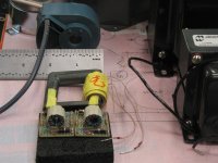
Here is the magnetics package for the 400W full bridge phase modulated converter. (The big iron in the background, for comparison, is for a 200W line frequency power supply for a 16W class A tube monoblock using 300b P-P.)
The "big" U-core was used with the HV potted secondary and 80T litz wire homemade primary in the yellow tape. There is a small air gap, not for DC but to add inductance for the switching scheme.
The mounted toroids are homemade gate drive transformers using a small ferrite toroid wound with loosely twisted #30 kynar wire wrap wire. The extra capacitive coupling functions as mixed drive and these worked really well.
The sconverter used an OTS controller and dual MOSFET driver chips with controlled edge rates.
A <100W converter package would be much smaller but then 2-4 of them are needed depending on the topology.
Michael
Attachments
smoking-amp said:Re: el'Ol
"....aren´t there semiconductor diodes in the signal path?"
Yes, rectifier bridges are on the HV side feeding the tube plates. (matching of the diodes might be helpful since the HF AC switches between diode pairs).
As these are cascaded low voltage rectifiers one could ask why he didn´t use one vacuum diode rectifier instead. For efficiency reasons? And would selenium diodes be a compromize (efficiency vs. harmonic spectrum)?
Re: el'Ol
The reason for using a string of low voltage diodes is to break up the high voltage windings into smaller sections. At 250 KHz, distributed coil capacitance of a HV winding is a killer for switching performance, so a common technique is to make several lower voltage windings and then sum the DC voltages after individual rectification. (this coil capacitance explanation would be for a Berning type design; the switched capacitor version necessarily uses cascaded capacitors and diodes for its voltage multiplier, so both schemes have lots of diodes)
Although it is possible to use pi-wound coils like used in TV HV flybacks to reduce coil capacitance. This takes special winding equipment though, suitable only for mass production. But leakage inductance between primary and secondary then becomes a problem, and at 250 KHz, leakage inductance is a killer for power transfer too. TV flybacks work by using the leakage inductance for the flyback effect and operate at a lower 15 KHz.
From what little I know about selenium rectifiers, they have high internal resistance, and give off toxic smoke if overheated. So I would avoid them. Tube rectifiers also have high internal resistance, which would not be favorable for this application. I'm afraid the 6AL5s are still un-employable here except for a rack mount sized headphone amplifier maybe.
Don
- Status
- This old topic is closed. If you want to reopen this topic, contact a moderator using the "Report Post" button.
- Home
- Amplifiers
- Tubes / Valves
- Another kind of hybrid