A simplified impedance converter for DIYers
I think the Berning and Switched capacitor impedance converters are clearly too complicated for the average DIYer to tackle except maybe to buy as a kit. So here is a shot at making a very simple design. This is untried as of yet, but shouldn't be hard to check out.
One of the simplest switching converters is the Boost converter. It uses one transistor for switching (with a nice ground referenced gate drive) and an inductor for current charging and a diode. When operated with 50% duty cycle it produces a triangle wave current output + DC current, and a voltage step up of 2x. And has no isolation between input and output. Obviously a little underwhelming so far.
But now some fix-ups.
By using two of these Boost converters, running 180 degrees out of phase at 50% duty cycle and summing their outputs, we can eliminate the triangle wave current, so this now becomes ripple free. By putting a secondary winding on the inductor, we can get the additional voltage step up needed for tube voltage use, like 10 to 1 say. Simplified schematic attached. Only two transistors and two inductors and two diodes.
Seems simple enough, but in the next post I will show how to do this with just one transistor.
Don
Attachments
One transistor clapping
Here it is.
One transistor, one transformer/inductor, two caps. (C2 can be deleted here) and one diode. Although the design of the transformer/inductor is much more complicated here. This design has no ripple on the input current or the output current, and has isolation betwen input and output. A somewhat simpler design is possible without the isolation. Obviously, this is based on the Cuk converter, I shamelessly have copied it from the Cuk book. (the name is pronounced shuk, not cook unfortunately) A Mosfet switch would be more appropriate these days of course.
For either of these new designs, two such units are needed for a P-P output stage (just like for the Berning or SCIC designs), one for each tube. The other unit would use a P channel Mosfet and a minus LV supply for the simplest gate drive.
I should add, that for this 2nd design (Cuk), the duty cycle can be varied to adjust the voltage ratio (hence impedance ratio) and it still maintains zero ripple current on the input and output. So one could have an adjustable output xfmr. An "impedance adjust knob", a nice feature for experimenting with tube designs.
Some compromise in efficiency would be required for either of these to avoid EMI generation by slowing down the Mosfet transitions.
Don
Attachments
What I can imagine is that the switching thing would be easier for ESL people. Do you think they would get along with a simple modulator->amplifier->transformer->rectifier->inductor->stator scheme? They wouldn´t need a capacitive coupling after the stacked vacuum diode rectifiers to get the signal on ground.
What do you think of such a beast, if to use it instead of a tube?
http://www.ortodoxism.ro/datasheets/powerint/TOP223Y.pdf
http://www.ortodoxism.ro/datasheets/powerint/TOP223Y.pdf
"What I can imagine is that the switching thing would be easier for ESL people."
Interesting idea, to convert to higher voltages for ESL. I wouldn't say it couldn't be done, there are obviously HV Mosfets available. But analog VHV (4-5KV) is bad enough, doing switchmode VHV would be really pushing it.
I guess the Mosfet switching could be restricted to the B+ HV range, and the very HV side of the ferrite xfmr could be tube rectified to the ESL panel. (But the ferrite xfmr would still need partitioning into lower voltage sections with a lot of recitfiers.) Or use the capacitance Volt multiplier (even more rectifiers though).
The beauty of the Berning and Switched Capacitor schemes is that they only have to handle 8 Ohm speaker type voltages (36V to 65V say). This is homefield for switcher technology.
-------------------------------------------------------
"What do you think of such a beast, if to use it instead of a tube?"
Not sure what you mean here: tube replacement via class D or OT replacemnet via Berning or related schemes.
The part is just a Mosfet and PWM controller chip merged. Fine for high volume low cost stuff. But for DIY I would prefer the Mosfets to be separate, cheaper to replace when they blow out from experimenting and more flexible if you decide you need a better/bigger part.
As far as making an OT replacement switcher, one needs a ripple free design (at least on the speaker side). A simple Buck or Boost conv. won't do it.
-------------------------------------------------------
I need to point out a correction to my simplified dual boost converter xfmr design a few posts above. I mentioned it was ripple free on input and output, but it is only ripple free on the LV, or speaker side. The tube side would still have some HF saw tooth wave on the current/voltage. This may not actually be a real problem, since the speaker side is what matters, but it needs testing to check this out.
The Cuk converter OT above however is really ripple free on input and output. Not sure how well it maintains that though if you change the duty cycle however (ie, change the impedance control knob). The complex ferrite xfmr it uses requires specified leakage inductances and turns ratios to achieve the ripple free operation mode. These might need tweeking if one changes the duty cycle.
The possibilities for a switching converter are still not exhausted. There is a technique which is called ripple steering (nowadays) that can be applied to simple converters to make them ripple free. This scheme was actually invented in vacuum tube days for power supply ripple reduction (its in RDH4 and "Electronic Designer's Handbook" 1957 by Landee, Davis, Albrecht). Its been re-discovered numerous times since then and patented over and over again.
If someone wanted to do a really archaic switched converter, the old DC to DC vibrator conv. units for car radios did exactly the Berning scheme (switching, xfmr, sync. demod.). Unfortunately they vibrate in the audio range, but if one could get two of them to operate 90 degrees out of phase, the overlap between the phases would make this largely inaudible since there would always be a conducting path. Makes me wonder if some mercury wetted reed relays could implement the Berning conv.
Don
"simple modulator->amplifier->transformer->rectifier->inductor->stator scheme?"
Oh, I just noticed you were suggesting a somewhat different scheme. Making the tube amp itself operate at high frequency then demodulate. No doubt the tube amp could handle this, but the HF HV xfmr after it is problematical I think. Would seem easier to me to just use VHV tubes for the audio directly and skip the xfmr. Usual solution here would be transmitting tubes. I myself stay away from such VHV stuff, too dangerous.
Don
smoking-amp said:
If someone wanted to do a really archaic switched converter, the old DC to DC vibrator conv. units for car radios did exactly the Berning scheme (switching, xfmr, sync. demod.). Unfortunately they vibrate in the audio range, but if one could get two of them to operate 90 degrees out of phase, the overlap between the phases would make this largely inaudible since there would always be a conducting path. Makes me wonder if some mercury wetted reed relays could implement the Berning conv.
Don
You probably forgot about the main idea, to eliminate a huge output transformer...
smoking-amp said:
-------------------------------------------------------
"What do you think of such a beast, if to use it instead of a tube?"
Not sure what you mean here: tube replacement via class D or OT replacemnet via Berning or related schemes.
I mean total replacement of output tubes and transformers.
Take 4 such devices with transformers and rectifiers and make a bridge from their outputs.
"You probably forgot about the main idea"
You could be right, in fact I'm having trouble remembering exactly what this thread was supposed to be about anymore. I think we started out on using accurate complementary P-P for SE emulation. At least it did have -something- to do with output xfmrs. But really more about tube emulation and anti-tube emulation I guess.
Michael, have we drifted too far off course?
"to eliminate the huge output xfmr"
Hmm, well the old vibrators ran at maybe 400 Hz, the DC/DC transformer shouldn't have been all that big. But I guess you mean the vibrator frequency would not work for an audio output conv. due to frequency aliasing problems.
"I mean total replacement of output tubes and transformers."
"Take 4 such devices with transformers and rectifiers and make a bridge from their outputs."
So you do mean class D? PWM control? Is this still HiFi?
What about using a switcher to make a low loss current source?
Could be "anti-modulated" by PWM for the opposite P-P device to the SE tube. Or could be co-modulated by PWM for assisting the SE tube. But I think this still needs to be better than just the usual PWM, ie., no ripple current. This takes either two 180 degree, 50% duty, switched inductors for a fixed current, or something like the Cuk for variable current. Still, I'm a bit leery of trying to actively modulate with PWM, really just class D.
Don
This thread has been an incredible exploration of alternative hybrid output stage technology, and I wouldn't dream of imposing limits.. Having said that I personally am interested in tube amps and closely related circuits.
At first I was baffled by the OPT replacement idea but here's how I think I would do it. I'm still not sure about this; something doesn't seem correct but I can't find any error.
The basic idea is to down convert from the tube load impedance at B+ to Zout, and present the output as a balanced totem pole DC connection. The tube balance has to be good, maybe servo control or current mirror.
It seems like in class A the load would share the same way as with a conventional OPT, i.e. each tube sees 1/2 the total so each transformer ratio should be equal to the desired step down in this circuit since the secondaries are in series.. There might be several windings or toroids in series on the primary side and in maybe in parallel on the secondary side on each leg of the push-pull.
I'm still thinking this one through but here it is anyway:
Attachments
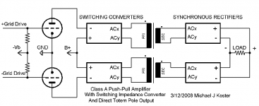
"I'm still thinking this one through but here it is anyway:"
This would be the straightforward way of converting with drive power from the tube side. I was going to say just like Tubelab's, but after looking at his schematic again I see a problem there due to the capacitor in series with the speaker. The tube idle current will charge the capacitor up, and the voltage across the tube will collapse. Maybe this was part of the problem with the Fets roasting.
The synchronous rectification approach, and two converters besides, will use a lot of Mosfets though, and half of them at least will require floating gate drives. I think you will still also need some diodes in series with the sync. rect. Mosfets to protect them from reverse audio voltage.
It's really pretty tuff to equal the Berning design for economy of parts and effectiveness, even though it still uses a lot.
------------------------------
On my simplified converter ideas posted above, I have some bad news. The current ripple on the tube side of the dual boost design means there is a minimum current before conduction becomes discontinuous between switching cycles. So operation of the tubes would have to be class A to maintain continuity. Not real attractive, but useable still.
The Cuk converter avoids that one with it's zero ripple, but suffers another problem common to all the simple inductor mode converters. They have essentially a current source output Z, not a voltage source. Which means it has poor voltage regulation without feedback. This is the same problem (well one of them) that class D amplifiers suffer. So anything transformed thru these simple converters will look like pentodes and need global feedback.
That got me thinking about the switched capacitor imp. converter. It has output Z matched to the nominal load. Much better than a current out Z, but not good for a high damping factor (1). So it still needs feedback to get the damping factor up. The SCIC can be designed for a lower output Z by using bigger capacitors, but then the shunt C on the tube goes up. I guess one could design for about the same shunt C as conventional OTs and so get Zout down by 5 or 10x if no feedback is contemplated.
The Berning Zout is nominally/ideally the tube plate Zout transformed down. But in practice, it has the xfmr leakage inductance suffered at the HF in series. (this is not a problem in the resonant mode SCIC) Until I build one, I couldn't say authoritatively how big a factor that is, but a rough guess would be that the xfmr bandwidth is maybe a couple of MHz (and switching is operating at 250KHz), which would place the Lleak at about 1/8 of the nominal load Z. So maybe a damping factor of 8 is possible without feedback. But one would really have to test this. It's very dependant on the xfmr winding technique. I see Berning uses pot cores in his amplifier photos. Toroids can get Lleak a bit lower I think as well as Cshunt decreased too with multifilar 100% fill winding. But pot cores are so much easier to wind.
With the four phase extension to the Berning design, it seems to me that one should be able to drop the switching frequency considerably. This would alleviate the xfmr leakage issue on the damping factor. Of cours the xfmrs get bigger then. And four of them. Is there some secret law about OTs have to be 3"*4"*5"no matter how you scheme?
What was Ken saying about those transonars? (desperation setting in here)
Don
Michael Koster said:I'm still thinking this one through but here it is anyway:
You don't need switcher supplies if you are driving from
the tube side. Drive both triodes SE, and bias into cutoff
with opposing square waves at the cathodes. Imagine a
6N30Pi twin triode as the top half of a cascode, above a
pair of switching mosfets. Let the tubes do the heavy
voltage blocking...
It is the synchronus rectifiers that are tricky. If the are
simultaneously on, its a dead short. If they are both
simultaneously off, there is nowhere for the inductor
to discharge but an arc... The overlap is a pain to get
right.
Fast recovery diodes are more cooperative, but there
is a forward voltage drop that makes them lossy....
And on the low impedance side, that can be significant.
I like the Berning design, cause it abuses simple diodes
that don't require fancy drive timing to prevent parts
from exploding. Who cares about a few diode drop on
the high voltage side? And the switch devices are all
kept to the low voltage end...
As for Transonars, Rosen type with about a 20x step-up.
Sometimes used for cathode backlight with a flat screen.
Probably the easiest way to find some for experiment.
Yes, the Berning design is elegant and effective. It has a number of advantages including replacing the B+ supply. Diodes are insignificant on the HV side, switcher is easier on the LV side. Both designs probably need to segment the primary to get the capacitance in series for the same reasons.
My design is just another way of doing it that drives from the tube side It does take more parts and basically needs gate drive transformers with well-designed timing. I guess I'm comfortable with that kind of design but by comparison there seems to be no advantage except it's not patented (yet). The output based drive appears to have some advantages.
Hmm. I have an old Hafler amp with blown up MOSFETS. It has a big bipolar DC power supply. I could prototype the output based drive scheme on this chassis. It is 150W/channel class AB SS so should be good for 20W class A easily.
More food for thought...
Michael
Topological Variants
Here are some topological variants on the Berning converter.
1st a Circlotron converter.
2nd a single power supply converter.
Output ground can be put at either end of the load here as indicated. Putting the ground at the power supply end is probably the best if using a switching power supply.
Don
Here are some topological variants on the Berning converter.
1st a Circlotron converter.
2nd a single power supply converter.
Output ground can be put at either end of the load here as indicated. Putting the ground at the power supply end is probably the best if using a switching power supply.
Don
Attachments
Here I am taking a clue from George's design, but adapting it to the undiriectional current flow for the Berning type converters (or SCIC).
Its seems a bit redundant to use two converters when we are only transforming a single signal. So I have done P-P to SE to P-P conversions here to get down to just one converter.
The switched mode CCS blocks are switched inductor current sources (minimal power loss). Their currents are arranged in accordance with the converters "turns" ratio in order to balance out (recall that the conv. is true DC to DC, so the CCS currents will balance out thru the converter).
Counting Mosfets (asuming two per CCS for ripple free currents) however still comes up to the same number as using two converters.
-----------------------------
I think there may be a new design option surfacing here.
1st, the two switched CCS's are current related by the same ratio as the converter ratio. Seems they could be combined using the same inductors with two windings on each core and using the same Mosfets for automatic current tracking.
Now I may be going out on a ledge here, but I am wondering if the converter itself could not be implemented some how using the same two switched xfmr CCS's as well. After all, the CCS cores have the same audio signal voltages imposed on them. Some more thinking called for here, but seems like the converter could just be deleted...... somehow.
Don
postmortem: I think I see how to do it. Back later.
Attachments
More ideas:
1. PWM CCS, one triode, capacitive coupled impedance matching transformer. Advantages: light PS transformer, gapless output transformer.
2. PWM VCCS, the same. Additional advantage: more power per tube.
3. The same, Darlington tube+ FET. One more advantage: smaller tube for the same power.
4. I am going to implement it as soon as finish Alligator project: it will be classical PP, but with additional FETs (A+C). Challenge: transformer limits gain in FB loops on high frequencies, it is needed for smooth approximation in cross-over region between A and C. Anyway I will try that. If failed, Darlington tubes + FETs.
4.1. Class C output transistors in parallel with tubes, before OPT.
4.1 Class C output transistors after OPT (low voltage HPS, low breakdown / high current transistors).
4.2. Transformerless class A tube amp, easier with NFB Kind of combination of my Swinnik project (SS A+C) and Tower project (tube driver and class A asymmetrical SS output).
Re: Topological Variants
I think that the current mirror output stage is a natural because it's DC self-balancing.
I like the way you show the tube and converter as a building block!
There are a lot of different topologies. These look like simple rearrangements of the basic totem pole load connection. Do the current loops differ in any way?
Yes, last night I was getting ideas for factoring out some redundant paths also but nothing concrete has fallen out yet.
I will need to study your CCS some more...
Michael
kenpeter said:Going Berning on top, AntiTriode on bottom?
I think that the current mirror output stage is a natural because it's DC self-balancing.
smoking-amp said:Here are some topological variants on the Berning converter.
1st a Circlotron converter.
2nd a single power supply converter.
Output ground can be put at either end of the load here as indicated. Putting the ground at the power supply end is probably the best if using a switching power supply.
Don
I like the way you show the tube and converter as a building block!
There are a lot of different topologies. These look like simple rearrangements of the basic totem pole load connection. Do the current loops differ in any way?
smoking-amp said:
...
I think there may be a new design option surfacing here.
1st, the two switched CCS's are current related by the same ratio as the converter ratio. Seems they could be combined using the same inductors with two windings on each core and using the same Mosfets for automatic current tracking.
Now I may be going out on a ledge here, but I am wondering if the converter itself could not be implemented some how using the same two switched xfmr CCS's as well. After all, the CCS cores have the same audio signal voltages imposed on them. Some more thinking called for here, but seems like the converter could just be deleted...... somehow.
Don
postmortem: I think I see how to do it. Back later.
Yes, last night I was getting ideas for factoring out some redundant paths also but nothing concrete has fallen out yet.
I will need to study your CCS some more...
Michael
"I like the way you show the tube and converter as a building block!"
Well, as they say, if you can't solve the problem, shrink it.
"Do the current loops differ in any way?"
No, nothing really new there. Still using the Berning-like uni-directional-polarity converters in the normal way.
"need to study your CCS some more..."
The last version with the switched CCS's is actually fairly straightforward: Since the converter can only handle one direction of current on both ends, I sum the 1st CCS current with the bi-directional tube output current to make it uni-directional for the converter. On the load end I just subtract the converted CCS current back out to get the original bi-directional tube current again. Only need one converter then, runs in unidirectional current mode all the time.
What then attracted my attention is that the two CCS currents are related by the same ratio as the converter ratio. So it seems the two switched CCS's could be derived from the same inductor/Mosfet with just some N:1 windings. Turns out one needs two inductors in series, with one of them having an N:1 secondary. Same Mosfet drives them both. For ripple free current, one then doubles up this whole shebang with 180 degree switching between them so ripple cancels when the matching currents are summed. So far, do-able I think. So two Mosfets and four inductors can replace one converter essentially.
My final speculation was on replacing the remaining converter altogether with another ratio'd pair of complementary CCS's. While one phase charges its current up it would be acting similar to the converter, and the opposite CCS's would be discharging or equivalently providing the offset currents. On the next half cycle, the top and bottom pairs reverse roles between conv. mode and CCS, etc. So far I haven't gotten this idea to work. But looks interesting enough to keep trying.
-------------------------------------
"Wait,....."
But then you need to double the number of tubes if you don't want half wave HF mixed in. Ie, need two tubes per full wave rect.
Don
My explanation of the two switching CCS's version needs a little fixing. First of all, it's probably easier to view it as the 2nd CCS is opposing the converter in feeding the load (so as to get bidirectional current into the load), then the 1st CCS on the tube side provides an opposite current summed into the converter from the tube side so as to null out the constant current on the output, leaving the bidirectional output current. In any case the conv. gets to operate in unidirectional current mode like it wants.
An obvious problem with the scheme is that it transfers power from the B+ power supply to the LV supply. No net power loss, but very inconvenient.
------------------------------
My final speculative scheme above, using complementary CCS sets and alternating between current op. CCS mode and voltage op. converter mode on opposite cycles, might be workable in theory, but runs into the practical problem that the CCS wants an air gapped xfmr core and the voltage conv. wants a non-gapped core. So, I'm giving up on it.
--------------------------------
Some summary thoughts.
The Berning scheme obviously does everything optimally except for requiring two converters for just one signal. (uni-directional current requirements on input and output.) It actually provides better performance at the lowest switching frequency above audio since this minimizes leakage inductance to give the lowest internal output impedance (ie, best damping). So going to 4 phase overlapped operation and dropping the frequency is a good idea for damping and also EMI elimination by slowed down switch slewing.
The Switched Capacitor Impedance Converter (SCIC) on the other hand performs better the higher the switching frequency.
This allows the capacitors to decrease in size and so reduces shunt capacitance on the tube. (higher frequency also allows one to decrease internal impedance, or equivalently increase the damping factor) Four phase operation is a must with its resonant operating mode. It also needs two converters for just one signal. (again, uni-directional current requirements on input and output.)
Zero current resonant switching eliminates most EMI problems here too. (well, the fundamental switching frequency still remains for both SCIC or Berning schemes.)
The SCIC can also be implemented using a step-up ratio in is xfmr/inductors to reduce parts count. Doing all the step-up in the xfmr/inductors (still one resonating cap.) would look like a resonant Berning version, but it still scales performance wise with higher frequency since the res. cap nulls out leakage inductance.
We need some real magic here I think to do better.
The simple inductive converters (Boost, Cuk) are simpler, but have pentode like output Z (they do however still convert power to a low Z load well.)
Only thing I see is to drop to single tube SE operation with one converter and put a switchmode CCS on the LV output side to balance it. (And Anatoliy will want to PWM counter-modulate that besides.)
Don
- Status
- This old topic is closed. If you want to reopen this topic, contact a moderator using the "Report Post" button.
- Home
- Amplifiers
- Tubes / Valves
- Another kind of hybrid