I think the dual pivot might be arranged so that the outside rear pivot bearing follows an ellipse, which would mean even more accurate tracking, but that brings me back to math, again, alas.
This is what my arrangement looks like, fixed main pivot, second pivot tracks the arc of an ellipse in quadrant 4 if centered at (0.0).
Doug this is really great work.
I just jumped out of bed to try something that I eye-balled from Steen's plot.
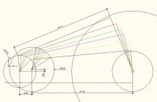
If you plot a line from the intersect of the the pivot circles to the midpoint of each line segment between the circumference of the 2 two pivot circles. Then it looks suspiciously like an arc of ellipse.
If you play with the 3 variables, pivot origin distance and radius of the two pivot circles, you should be able to get it spot on to the mathematical ideal.
This will remove the need for a track like in my own implementation at the possible expense of extra mechanical noise, but it certainly simplifies the design and you should be able to mitigate the mechanical noise.
Well done mister, this looks very promising.
I just jumped out of bed to try something that I eye-balled from Steen's plot.
If you plot a line from the intersect of the the pivot circles to the midpoint of each line segment between the circumference of the 2 two pivot circles. Then it looks suspiciously like an arc of ellipse.
If you play with the 3 variables, pivot origin distance and radius of the two pivot circles, you should be able to get it spot on to the mathematical ideal.
This will remove the need for a track like in my own implementation at the possible expense of extra mechanical noise, but it certainly simplifies the design and you should be able to mitigate the mechanical noise.
Well done mister, this looks very promising.
It is very close already.
An externally hosted image should be here but it was not working when we last tested it.
This thread is so interesting, ideas flowing all over the place.
I knocked up a wooden rig and my first effort hits the Loefgren protractor exactly on the two null points. Don't know about the rest of the arc but it looks good by eye.
Oh dear, Ronnie will be pleased, she thought I'd be doing some plastering in the dining room today
Now, where did I put those spare bearings?
An externally hosted image should be here but it was not working when we last tested it.
Update:
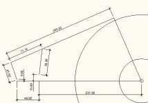
Its snowing outside, so the things I had planned to do today has to suffer. Another autocad hour has been rewarding. I dont think we have to implement elipses to this idea. There are so many parameters to "relocate" and I believe that playing around with armlength and pivot placing could bring us extreemly close to 100% tangential. Doug, I think you'r on to something
Steen
edit.: Center of 40mm radius circle is alligned with center spindle
Attachments
Last edited:
Update:
Its snowing outside, so the things I had planned to do today has to suffer. Another autocad hour has been rewarding. I dont think we have to implement elipses to this idea. There are so many parameters to "relocate" and I believe that playing around with armlength and pivot placing could bring us extreemly close to 100% tangential. Doug, I think you'r on to something
Steen
edit.: Center of 40mm radius circle is alligned with center spindle
Wow, thanks for the measurements. Interestingly, the thing I rigged up by eye has the following measurements. Small circle 40mm, big circle 56mm, between centres 40mm and the arm 500mm. So near as dammit and it certainly looks good by eye.
The horizontal pivots are easy enough but I assume the the vertical one will have to be on the arm itself as it would tilt if placed anywhere around the main pivot points. So rather like a long Dynovector with a straight headshell.
So long as its just in front of the secondary pivot, there will still be room for an arm lift.
More fun and games tomorrow then
To my experience, linear arm can easily outperform pivot arm.
What kind of pivot arm are you talking about? Linear arm uses linear bearing (air or roller) that travels from one location to the next. Pivot bearing stays in one spot. To achieve tangency does not always have to move linearly like parallel trackers. If you just prefer to stick with parallel tracker, then that's fine. But until you can compare a parallel tracker to a TANGENTIAL pivot arm, your argument cannot be conclusive.
I am not sure why it needs a guide mechanism. The guide mechanism you have adds one more contact point. It means adding more friction. What it needs may be just something like anti-skating device to add a inward force. This force can be added on magnetically or mechanically.
The guiding mechanism is necessary because there are conflicting forces at play that you need another force to geometrically regulate the travel or movement. My observation is that one segment is trying to swing inward to the spindle while the other segment is trying to move forward but since the joint of the two segments have only one pivot you still need another force to keep it tangential or "angling for 90°." Of course you can always try it with an actual arm and see what happens.
I can cad this up with motion analysts, vibration and flexible and send back as an edrawing .....
I dont even know what you are on about, but any input on the subject will be interesting. Bring it on
I have some initial thoughts about how to produce this arm, and beeing located in the northern wilderness, makes ebay a lovely shopping center.
Steen
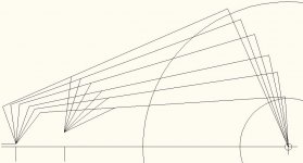
Fooled around today with some needles and cardbard, and found out that if you get it marginally wrong, it has a bad effect on tangens at the stylus point. By increasing the length of all four sides of the "square", this error becomes much easier to avoid. The new measurements I have come up with, are extremly close to 90 degrees all the way across the record.
Steen
Steen
Attachments
What I meant was I have a full computer aided design suite (solidworks) with FEA (finite element analysis) it also includes a motion analys for interrogating motions and angular descrepancies. The edrawing is a way for others with out the cad software to get a 3D model that can be measured etc
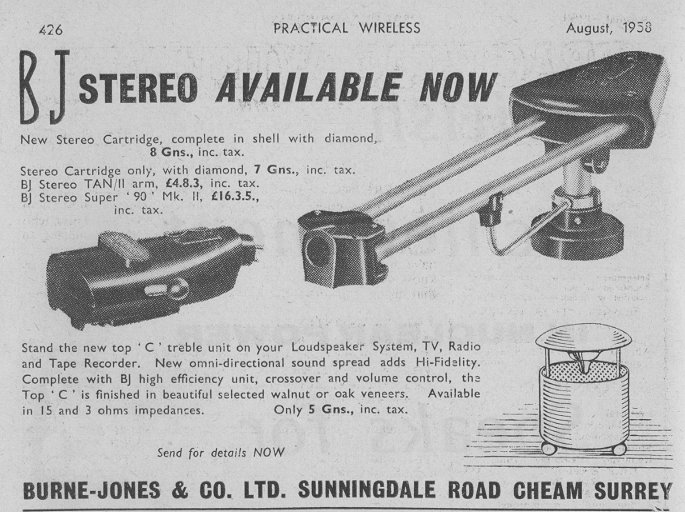
The four pivot design reminds me of the Burne-Jones arm with a longer vertical arm.
An externally hosted image should be here but it was not working when we last tested it.
An externally hosted image should be here but it was not working when we last tested it.

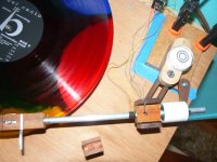
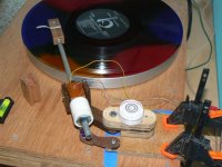
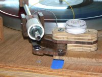
First Sound
I got this finished up last night and put it in the system with an AT95E at the business end.
It works. No stylus hunting, no skipping or mistracking.
There's more to do, but it has the crystalline quality I associate with LTs.
I got this finished up last night and put it in the system with an AT95E at the business end.
It works. No stylus hunting, no skipping or mistracking.
There's more to do, but it has the crystalline quality I associate with LTs.
Attachments
I got this finished up last night and put it in the system with an AT95E at the business end.
It works. No stylus hunting, no skipping or mistracking.
There's more to do, but it has the crystalline quality I associate with LTs.
Damnation....I'm going to need another arm wiring kit
A good sign - usually at this stage of the game, I'm caught up in technical listening, but this arm/cart combination pull me away from that and into just enjoying the music. There's a lot of detail and it so revealing it showed up the inadequacies of the DIY rim drive I put it on.
2wice - I hope you're still working on your project. I noticed in the drawing you posted at #903 that the centers of the two circles align horizontally. In my design and Steen's drawings the centers are offset. Am I seeing your drawing correctly?
Gus - yes, get to work. For checking alignment, a strip of graph paper or calendar page, anything with a series of perpendicular lines is convenient. Just punch a hole in one end for the spindle and rotate it as you move the arm. Or you can just attach something like a kabob skewer perpendicular to the headshell directly above the stylus position. If the other end stays centered on the spindle, you're good.
Steen - thanks. I've been at this long enough that there is reusable junk all over my shop. I used the measurements from the drawing in the post showing my model. Your drawings are excellent and I hope to see them converted to a working arm. Could you expand on what you mean by the "square" in #912? Your measurements in your second drawing are very similar to the ones in the arm I built.
Both you and Gus have commented on the importance of accuracy. In building an arm, it's important to get precise pivot points, but equally important to make sure the pivot axes are as vertical as possible. A good shop is a good thing, but there are adjustable work-arounds that will do the job so this really is something that a lot of guys could build.
Anybody who's going to build, check out "pre-loaded bearings." It's amazing how well bearings behave if you put them together that way.
canyoncruz - that's a very interesting drawing. I envy you guys who can do that kind of work. I wonder if that drawing shows geometry that applies more to something like the Burne Jones arm DD posted than to the Thales Birch geometry. It's very likely I'm missing something. What kind of information would you need for an edrawing? Would Steen's be sufficient?
DD - as always, thanks for starting this thread and helping to keep it alive. A lot of what I've done wouldn't have been possible without the photos you've found and posted and the encouragement I've gotten here.
Last edited:
- Home
- Source & Line
- Analogue Source
- Angling for 90° - tangential pivot tonearms