Please feel free to use my design, if you hav a cad-system I can even export the files to you, only demand is that you build more than one, and I get one of them. Maybe the pulling force can be nulled with something similar to anti skating
Please send me the file for auto cad. jimw10001 at gmail.com. Thank you!
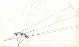
I've got some catching up to do. The photo shows three mounting guides I used that made my life a lot easier. The blue strip goes from the spindle to the main pivot. The large strip shows the arm and pivot alignment with the stylus in the outer position and was taken directly from the drawing. Its long edge goes along the arm center line and the angled edge goes to the two main pivot centers. The strip with perpendicular lines checks tangency.
Gus - Mark Kelly used a pivot arm counter weight on PLT he designed and built. There's a picture back a few thousand pages. Since I've had fairly good luck not using one, so I just never tried it. Grommet? Really? I bet he likes cheesy music. My listening room is a bit neater than yours, but absolutely nobody sees my shop. And speaking of shops, I would add one more to your list of reasons for building these things: It gets me out into that shop and that's a good thing in itself.
Steen - The skating question has been debated enthusiastically here. As a practical matter, I've found there are side forces that have to be countered. I use a very slight off-vertical bias.
DD - I think the two-tower, shared load idea has real potential, but I haven't worked on the details. Putting the vertical pivot between them might work, but there'd be some interesting construction challenges. The tower design I use lets me hang the main pivot between two bearings, which just makes me more comfortable. It also allows for a lower profile and CG.
I moved the arm to a Lenco B-52 yesterday and set it up pretty carefully using the guides in the photo. It has an AT120E at 1.8 gr. now and tracks very well. But more important, I think, is that I haven't truly enjoyed music this much for a long time.
Attachments
Hi guys,
I should stay out of this, but I have to add some food for thought.
dtut's arm is geometrically the same as an LT arm. Think of the second "guide" link as the magnetically coupled extension below(or nearly below the armwand axis. The radius of the guide rail circle/ellipse segment is equal to the secondary mechanical linkage.
Easier to implement(perfect for diy efforts), but far more friction prone...
And no decoupling/damping in the lateral plane....just added eff. mass.
I said it here before: A circle is an ellipse with both centers being congruent. Birch is a case where everything is centered around circle segments, - when an ellipse segment offers far greater freedom of placing all elements involved.
Skating will be present on all passive radial tracking arms, --- unless there is sufficient and properly directed displacement of the arm that is moving around the main axis:
Check out the LT arm. The base has a provision for tilting it in any direction. Not only would that allow to compensate for any discrepancy between the platter bearing orientation and the tonearm's vertical bearing orientation, the major benefit of such an arrangement is that a (small) tilt will create a restoring force that acts on the entire pivoted arm assembly. Like a pendulum, it will "find" the lowest position.
That alone brings an hitherto neglected force vector into play.
And that vector can be adjusted(length and orientation) such that it compensates completely for the drag exerted by the stylus which, (in conjunction with the resulting force vector not going through the main bearing) is what causes skating.
If one was to use a "conventional skating compensation mechanism, compensation being fairly constant over the usable radius of the record, the result would be unsatisfactory. The skating on dtut's arm decreases considerably with decreasing radius. A "vertical displacent compensation" will, by definition be non-constant and can be chosen to diminish with radius, hence compensate very closely to ideal.
The length of the main pivot arm together with the total displaced mass dictates the required vertical displacement.
If dtut was to replace the second "guide" arm with a thread, then, depending upon the attachment point of said thread, spring load that thread, friction could be greatly reduced. Having the thread wind or unwind onto a cam, any positional determination based on an ellipse, cycloid or whatever segment can be realized.
All the best,
Frank (Schröder)
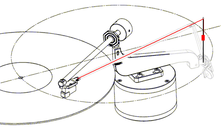
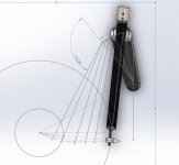
9" tonearm with no tracking error, but what to do with the friction pulling the arm joint open..??
One thing that is really bad with this thinking is that all records are off centered, and if you look at the needle it sways much more than what 1-degree tracking error from a 10" radial arm would even deliver. personally I don't see the benefit in no/low tracking error at the expense of added complexity or the non solid nature of the bearing in linear trackers.
Thank you for your drawings and providing another constructional option and some food for thought.
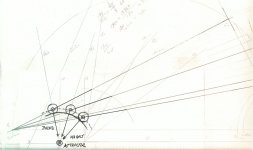
Looking at your provided drawing, I was initially not sure of what I was looking at. Then I realized the stationary pivot is in the front and the moving pivot is in the back of the turntable, which necessitate a rather long vertical arm with heavy counterweight. I found that to be rather counter-intuitive, even if I appreciate the extra geometric possibility. I'm curious why build the arm that way though?
It makes the vertical arm unnecessarily long and heavy that counters your avoidance of friction. Also why point the moving pivot so far away from the spindle to begin with? I would much prefer the Birch variants such as Doug's arm or the Schroeder LT that the swinging base is similar to the movement of a traditional pivot arm. Is adding one extra pivot that bad even when it eliminates tracking error, minimizing skating force, operates conveniently like a pivot arm, no air pump, lessens horizontal mass, no rollers and gliders, and no annoying rods hovering over the platter?! Also, I don't think the arm in your drawing will pivot the way you envisioned without a guiding mechanism: it has two linkages with one joint and it needs another force to guide its tangential path. Maybe it will self correct and find tangency on its own but I doubt it. The only arm I know that can do that is a fluid floating arm by another member in another thread.
Your graphic is impressive though. Wish I have that skill!
--------------------------------------------------
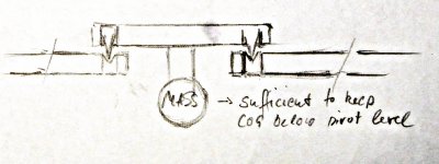
Here is another concept. Don't know how stable the arm would be. This uses 'Single' bearing and metal strips in liquid to balance the arm so azimuth doesn't change and also dampens the vibrations. Bottom strip is flat horizontal so it resist the rotational movement and Vertical strip runs parallel to the liquid so has least resistance. Again don't know how much stable it would be.
While I like your single-mindedness (pun intended) in achieving low bearing count, your approach is almost like making a linear unipivot arm that's always trying to stabilize azimuth. But a unipivot arm has a stationary bearing and yours is always moving and constantly trying to re-stabilizing itself and it seems rather belabored. I think a simple two bearing a la Cantus style probably works better. I admit a single bearing is attractive in concept. Perhaps you can try a magnet pointing down to avoid azimuth rocking. Or the magnet pointing up to lessen the mass. Another issue with a single ball bearing is that there's very little contact surface so it is prone to horizontal pivoting or twisting motion that should be avoided because once that starts to wriggle you loose tangency! Great drawing!
------------------------------------------
I should stay out of this, but I have to add some food for thought.
You are always and appreciatively welcomed to this thread, Frank!
Not only you're a real theorist, unlike me, but you are, to use an American football analogy, a real quarterback who scores touchdowns!
And I'm a Monday morning quarterback.

If dtut was to replace the second "guide" arm with a thread, then, depending upon the attachment point of said thread, spring load that thread, friction could be greatly reduced. Having the thread wind or unwind onto a cam, any positional determination based on an ellipse, cycloid or whatever segment can be realized.
Can the string be mass loaded like your early Thales experiment?
Last edited:
Hi,
Yes, that string could also be tensioned by, say, a dropping weight. But, just like in the Thales/Schröder hybrid pictured, such a dropping weight will excert a force on the arm assembly. The thread's "dropping"(pivot) point would be stationary and such a dropping weight could even substitute the vertical displacement skating compensation, - but not as close to ideally.
The very first conceptual LT model featured a string instead of a magnet/rail positioning system. Worked well, but the magnetic coupling has additional advantages... like lateral damping of the fundamental arm cartridge resonance frequency through induction of Eddy currents.
@dtut: To reduce total friction, you could retain the ball bearings for the main arm/pivot bar and try two cup and spike bearings for the guide arm... placing the cog of the guide arm below the bearing cup level required for stability. Mount the spikes eccentrically and you have a means to adjust the eff. length of the guide bar within the boundaries of the chosen eccentricity. Allows for finetuning the geometry...
Cheers,
Frank
To reduce total friction, you could retain the ball bearings for the main arm/pivot bar and try two cup and spike bearings for the guide arm...
The two cups + spike idea reminds me of the bearing in RS Lab headshells.
An externally hosted image should be here but it was not working when we last tested it.
Direct, if you look at The picture from beneath you see the two pullies, they are belt or thread connected and thus locked in rotation together, this leaves us with an arm with low vertical mass, but more horizontal mass, the arm opens in a scissor like manner as the cartridge moves over the record surface.
Hi guys,
...
That alone brings an hitherto neglected force vector into play.
And that vector can be adjusted(length and orientation) such that it compensates completely for the drag exerted by the stylus which, (in conjunction with the resulting force vector not going through the main bearing) is what causes skating.
...
All the best,
Frank (Schröder)
Let’s not neglect said force vector any longer. Please provide a diagram to illustrate your point for us. You also refer to different methods of applying bias, which is really the application of anti-skate. True, the magnitude of skating in multiple linkage design arms can vary widely across the record surface and, if the skating magnitude/position characteristics are known, an anti-skate method could be designed to accommodate with a matching ‘reverse’ characteristic. Problem is, stylus drag force varies with groove modulation intensity, and so is never correct for all records, or even for different areas of the same record. Witness the ever present volumes of posts on the vinyl websites from people continually twiddling with anti-skate adjustments, settings, and disagreeing on proper methods for dealing with it. Here we now have ‘neglected force vectors’ in the mix.
Rather than engage in debating theory, I propose a simple litmus test for determining whether a given arm design is susceptible to skating forces or not:
Take a string 12” or longer, it doesn’t really matter, and tie it to the headshell or the cartridge body so that it stretches straight out from the cartridge and in line with the stylus. Balance the arm for zero VTF and let it float above the record surface. Now, gently pull on the string along the axis of the cartridge and in line with the stylus. In a true linear tracker, the arm will stay put as the string becomes taut. In a conventional pivoted arm, the arm will veer towards the spindle as the string becomes taut. With a multiple linkage design arm, if the arm veers in either direction over any tested area of the record surface, then it is susceptible to skating effects induced by stylus drag, at that tested area.
Direct, if you look at The picture from beneath you see the two pulleys, they are belt or thread connected and thus locked in rotation together, this leaves us with an arm with low vertical mass, but more horizontal mass, the arm opens in a scissor like manner as the cartridge moves over the record surface.
Ah! Thanks for the clarification. You really put a new spin on this! I've seen arms with pulley at the headshell and fixed pivot areas before, like the one below, but not in the way you designed it. Very interesting! I still hope you will build it one day!

I wonder if you can apply the pulley design on a Birch style arm like Doug's creation or the Schroeder LT?
Last edited:
Not really sure AutoCad is possible, this is 3d modeling. I can make an IGES file, but not really sure Autocad would absorb it.
Can you export .3ds file? Thanks again!
Thanks DirectDriver and Super10018.
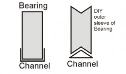
Yes tangency would be an issue. Sorry didn't mentioned earlier. The V Channel will hold the bearing in place and would be lateral guide. The puddle will be filled with liquid so as horizontal metal strip would resist rotational movement and with appropriate weight of metal strips serve as a stabilizing pendulum. I wonder instead of V channel if we put square channel holding the bearing would it be a good idea ? OR If one can DIY custom outer sleeve of bearing as shown in the cross section Picture ? Hope I am not boring you all with abstract ideas.
Regards
Attachments
Hi Doug
My drawing as is was just a quick visualization to see if I can see the ellipse.
I'm still going to try the 2 pivot + guide rail once I get the correct material.
My drawing as is was just a quick visualization to see if I can see the ellipse.
I'm still going to try the 2 pivot + guide rail once I get the correct material.
2wice - I hope you're still working on your project. I noticed in the drawing you posted at #903 that the centers of the two circles align horizontally. In my design and Steen's drawings the centers are offset. Am I seeing your drawing correctly?
Hi DirectDriver,
See attached sketch, - not really like the RS Labs ...
Hello diyrak,
I'm well aware of all the factors affecting skating force. Though one should accept the MANY imperfections and limitations of vinyl playback before going into it, a quest for improving one or several of those issues may lead to (temporary)neglection of others that are sufficiently lower in effect.
Otherwise we'd be constantly talking about the quality of stylus contact area polishing, vinyl formulations and their friction coefficient, torque required to bend/twist the inevitable wiring, etc...
Skating can take on many forms. Following your "pull a string attached to the front of the arm" -postulate, a straight line linear tracker does what you claim. But if I were to mount such an arm so that it isn't level, skating occurs(depending upon the direction and angle of the slant). If your wiring isn't infinitely limp, skating occurs. A blank record test will show this very clearly.
So skating can have many reasons, the geometry of pivoted arms being(usually the biggest) one of them. The task is to avoid as many causes for it and compensate for the remaining force WITHOUT creating a side thrust on the cantilever, which can lead to non-linearities easily more audible that those stemming from a deviation from tangency.
I'll try to provide a drawing, but have a rather busy schedule right now, so excuse me if that does materialize right away. I'm sure that you could derive your own drawing based on my description.
Cheers,
Frank
Attachments
Hi DirectDriver,
See attached sketch, - not really like the RS Labs ...
Hello diyrak,
...
I'll try to provide a drawing, but have a rather busy schedule right now, so excuse me if that does materialize right away. I'm sure that you could derive your own drawing based on my description.
Cheers,
Frank
Please, I'd like to see it from you. I'll monitor this thread and watch for it.
Thanks
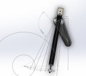
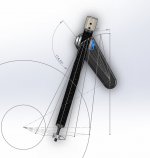
More shots, different take on straight tracking, but also showing the problems in this approach as the friction will pull the motion open, thus creating a growing skating force on the cartridge, some counter force need to be applied.
Attachments
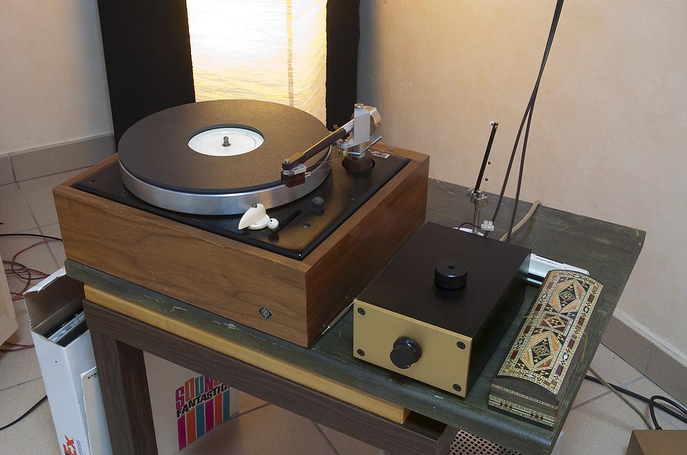
During a break in plastering walls, a quick pic of mine, awaiting wiring.
The arm itself needs better bearings as there is some play but I have something suitable in the spares box. Needs a bit of finishing but let's see how it works first!!
Back to walls
The arm itself needs better bearings as there is some play but I have something suitable in the spares box. Needs a bit of finishing but let's see how it works first!!
Back to walls
An externally hosted image should be here but it was not working when we last tested it.
two quick drawings
The first drawing shows my original intention which was a cam with the guide arm bearing as a cam follower. There was a lot of friction and noise so I ditched it and went with the two bearing pivot.
The second drawing shows a possible implementation of what Frank has described - I think. If it's anywhere close to possible, it could evolve into an ellipse - I think.
Hi Frank and welcome back. Thanks for your suggestions. I heard a political science theory professor say that every time he thought he had a real good idea he found Plato coming back the other way. I know how he felt.
Attachments
Not as bright as I think I might have been
Hmm........
My engineering needs a refresher course. The whole thing felt as loose and smooth as most of the arms but it just won't track. Obviously not as free running as I thought.
Somewhere, one or more of the bearings is clearly not set up properly, probably not dead on 90 degrees. the metal section is a little flexible so it probably didn't show up the duff section as much as a rigid bar would have done.
I can't be bothered to re-engineer this one at the mo as the linear tracker will be here in a couple of days and I will want to concentrate on that.
Interesting stuff though, so it will go on the list but for the time being will join the rapidly swelling 'experimental' filing system.
Will watch any others with great interest.
- Home
- Source & Line
- Analogue Source
- Angling for 90° - tangential pivot tonearms