gus 3049,
That's a good looking effort. It's a shame it apparently didn't work out. I was hoping we could compare notes.
A couple of questions for when you have time: What cartridge did you use and did you try removing the main pivot counter weight?
Hi Doug,
The cartridge I use for testing all these arms is an old Sony, not sure of the model number but it tracks very happily in all the conventional arms at 2.5 grammes and sounds OK. Once I'm sure stuff works, I can then put a decent cartridge in to see what the sound is really like.
I didn't try removing the main weight. I will try that at some stage.
I'm busy fighting our linear tracker for the time being. The damn thing sounds fantastic, it moves incredibly freely and yet, every time it plays, no matter where I start across the LP, it goes for 4mm and then stops!! Some sort of loading taking place on the bearings but I can't figure it out. If my genius brother in law has no suggestions, I'll post it here (or in my other thread) and open it up to see if anyone has any ideas.
The whole thing felt as loose and smooth as most of the arms but it just won't track. Obviously not as free running as I thought.
Somewhere, one or more of the bearings is clearly not set up properly, probably not dead on 90 degrees. the metal section is a little flexible so it probably didn't show up the duff section as much as a rigid bar would have done.
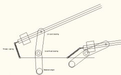
You can't give up now. I'm still waiting for parts, so at the moment I'm just a theoretic engineer. What if we reduced the mechanical ball/needle bearings to one instead of four. A simple unipivot straight arm, anchored at the end with a string and a spring
 . The spring will have to be just pushing enough to keep the thread straightened all the time.
 Steen
Attachments
You can't give up now. I'm still waiting for parts, so at the moment I'm just a theoretic engineer. What if we reduced the mechanical ball/needle bearings to one instead of four. A simple unipivot straight arm, anchored at the end with a string and a spring
Steen
I leave the designs to the real engineers, I just try stuff!! I haven't given up, it's just on hold whilst I struggle with the parallel tracker. I went to sleep last night trying to figure it out and I woke up the same way. Sadly, in this case, the brain didn't do its stuff during sleep.
My genius brother in law is 'thinking about it'. I'm plastering walls
Been playing with the math.
This is the formula for the ellipse my track needs to follow for 0 deg tracking error.
Here is the plot.
Plot
This is the formula for the ellipse my track needs to follow for 0 deg tracking error.
An externally hosted image should be here but it was not working when we last tested it.
Here is the plot.
Plot
2wice,
You've made impressive progress with the math. Have you worked out a way to build an arm that follows that arc?
Not quite yet but nearly there. (on paper anyway)
This one is obsolete, too complex. I've got a simpler design that I'm hoping will work.
An externally hosted image should be here but it was not working when we last tested it.
An externally hosted image should be here but it was not working when we last tested it.
The biggest problem is the change in length between the primary and secondary pivots.
Trying to shoehorn a complex problem into a simple mechanical solution is near impossible.
I'm trying something like this now. Not as complex because you only need a small part of the ellipse.
An externally hosted image should be here but it was not working when we last tested it.
Here are some further mock-ups of the design.
I'm not inferring that this will work but only that it was the simpler way of tracking the arc of the ellipse.
Video
Even if this is a futile exercise I still learned a lot.
I'm not inferring that this will work but only that it was the simpler way of tracking the arc of the ellipse.
Video
An externally hosted image should be here but it was not working when we last tested it.
An externally hosted image should be here but it was not working when we last tested it.
Even if this is a futile exercise I still learned a lot.
2Wice.
I'm looking at your mock-up and try to think out of the box, but I just don't get it
Is it a unipivivot arm, or is it bolted so that the cantilever has to move all the parts?? Looks awesome anyway.
Steen
Hi Steen
Thank you.
In this mock up there are no vertical bearings.
This was just to model the tangency of the moving pivot.
The vertical bearing will have to be sorted out still.
2wice,
You and gus 3049 are in serious contention for the audio sculpture prize - the drawings and the video are beautiful. Both of you are taking LT development in great new directions.
Are you going to try to implement it as drawn? Will it involve linear bearings and do you think they'll be free enough for the stylus to move them?
One way or another, I hope you're able to build a successful arm. Please keep posting.
Hi Steen
Thank you.
In this mock up there are no vertical bearings.
This was just to model the tangency of the moving pivot.
The vertical bearing will have to be sorted out still.
It looks a bit as though I've been doing some plumbing
My wife keeps asking if it couldn't be a bit simpler. I just suggest that as it works, it should be left alone. I'm looking forward to seeing how this works in practice. The bearing count in our linear tracker is mounting up but this one uses linear bearings. The machining accuracy is presumably, going to have to be spot on. It's certainly going to look great. When does it proceed to reality?
Are you going to try to implement it as drawn? Will it involve linear bearings and do you think they'll be free enough for the stylus to move them?
One way or another, I hope you're able to build a successful arm. Please keep posting.
Hi Doug
I'm still investigating if it's feasible. I'd like to try and build it but the tolerance are very close, can be done but pricey. So far the most cost effective method of manufacturing the linear bearings would be to go waterjet cutting of multiple discs. That would give repeatable 1 micron precision as well as being cheaper than machining to about 5 micron.
I've tried to calculate if the degree of freedom (drag) will be low enough. It looks like it is but I'm still working on it. Like this.
This is the formula for air shear drag is dependant on the speed and we are working with very very low speeds that are in our favour, and it will be exponentially lower than any mechanical bearing anyway.
An externally hosted image should be here but it was not working when we last tested it.
The stylus drag force described here only has to be marginally more than the air shear drag described above to motivate the bearing to move, but there's more motivation for it to move described below. The stylus drag force is dependant on TT mechanical properties.
An externally hosted image should be here but it was not working when we last tested it.
This is the steady state of the bearing air gap pressure. H1=H2
An externally hosted image should be here but it was not working when we last tested it.
This is the off axis state of the bearing from groove tracking. H1>H2
An externally hosted image should be here but it was not working when we last tested it.
This is the air gap pressure during steady state.
An externally hosted image should be here but it was not working when we last tested it.
As soon as H1≠H2, hopefully the air gap pressure will try to seek an equilibrium across the bearing face, motivating the bearing to compensate, this can only happen if it moves.
These are only my ideas, I'm not a scientist so I cannot vouch for the accuracy or feasibility of it but I'm hopeful.
Hopefully stylus drag will be the higher force, then it will work.
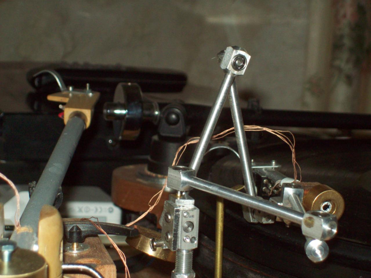
Gus' creation
I should have mentioned this long ago. Our member Gus has an interesting thread that shows some of his fascinating creations and one of them relates to this thread, that is, a tangential pivot tonearm(TPT). For those who follow this thread and not aware of his creations, please go check out his thread and give him some props. It even included a video.
I should have mentioned this long ago. Our member Gus has an interesting thread that shows some of his fascinating creations and one of them relates to this thread, that is, a tangential pivot tonearm(TPT). For those who follow this thread and not aware of his creations, please go check out his thread and give him some props. It even included a video.
An externally hosted image should be here but it was not working when we last tested it.
An externally hosted image should be here but it was not working when we last tested it.
Don't know If this has been said yet ? One idea I had was a cam slot that holds the arm. A simple sensor determins where on the record you are and moves the cam. This allows the engineering to be that of schools robots using a Raspberry Pi or whatever. For simplicity a simple clock type drive could be used, a gearbox + AC motor. This would get it working. Listening tests would say if worth doing a stepper drive. In fact a 12 V stepper can work on AC. I suspect this would reduce the error to 25 % of usual. Frank Derny perfected the Zero 100 arm. Alas it was never seen on the Zero 100. Frank went on to perfect Williams racing cars.
LT
Just found some new pictures of the Schroeder LT to share. Sans counterweight. The simplicity of it makes it really elegant looking.
Just found some new pictures of the Schroeder LT to share. Sans counterweight. The simplicity of it makes it really elegant looking.
An externally hosted image should be here but it was not working when we last tested it.
An externally hosted image should be here but it was not working when we last tested it.
An externally hosted image should be here but it was not working when we last tested it.
An externally hosted image should be here but it was not working when we last tested it.
Last edited:
Wow... Took some time to look at this thread, way too much info here to digest in a short period. You guys amaze me with your knowledge and skills, some of the arms you are building are impressive, I have neither the time nor the facilities to embark on such endeavors however this topic of zero tracking error is near and dear to my heart as I have been interested in methods of reducing the tracking errors associated with traditional tonearm geometry since I first pondered the idea in the late 70`s. I remember looking in on this thread a few years ago when it was much smaller but still found it interesting, I have since then been keeping my eye open for a used specimen of the tangential/linear tracking ilk.
Having said all that I am motivated to improve what is a niggling issue with non-linear tracking, I have also not been a fan of electronic methods to move a tonearm in a so called linear fashion, it seemed to me that the stylus would always be in a state of error with too much pressure on one or the other side of the groove.
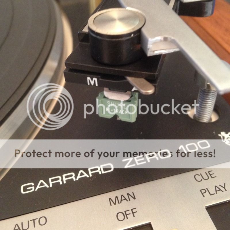
Recently I acquired the much maligned Garrard ZERO 100 from the family of a local deceased man who lovingly cared for his Garrard for many years. Other than some of the lubricant getting a wee bit viscous all else appears to be in order and near mint condition including the dust cover, what a Rube Goldberg contraption that thing is... Not a fan of the dust cover.


As I have never been a proponent of automatic turntables I am considering gutting all of the mechanisms not associated with platter rotation (of course I will leave the cue lever intact) thereby leaving myself with a manual turntable with an interesting attempt at tangential pivoting tonearm. I will of course still be left with an idle wheel turntable which is less than desirable in my mind.
I have looked at the headshell, I do not like the contacts (brass fingers), what a horrible idea that is, I need to devise something else to support the cartridge and re-wire the tonearm so that I can connect directly to the cartridge. Also the pivot point does appear to be reasonably centered over the stylus which of course improves upon error free tracking however the bearing is a bone of contention with me, I would prefer to see a jeweled bearing arrangement like a clock but I wonder about the jewels ability to deal with the loads. I suspect this will be a work in progress for some time.
Thanks for sharing your expertise and for keeping this thread interesting.
Having said all that I am motivated to improve what is a niggling issue with non-linear tracking, I have also not been a fan of electronic methods to move a tonearm in a so called linear fashion, it seemed to me that the stylus would always be in a state of error with too much pressure on one or the other side of the groove.
Recently I acquired the much maligned Garrard ZERO 100 from the family of a local deceased man who lovingly cared for his Garrard for many years. Other than some of the lubricant getting a wee bit viscous all else appears to be in order and near mint condition including the dust cover, what a Rube Goldberg contraption that thing is... Not a fan of the dust cover.


As I have never been a proponent of automatic turntables I am considering gutting all of the mechanisms not associated with platter rotation (of course I will leave the cue lever intact) thereby leaving myself with a manual turntable with an interesting attempt at tangential pivoting tonearm. I will of course still be left with an idle wheel turntable which is less than desirable in my mind.
I have looked at the headshell, I do not like the contacts (brass fingers), what a horrible idea that is, I need to devise something else to support the cartridge and re-wire the tonearm so that I can connect directly to the cartridge. Also the pivot point does appear to be reasonably centered over the stylus which of course improves upon error free tracking however the bearing is a bone of contention with me, I would prefer to see a jeweled bearing arrangement like a clock but I wonder about the jewels ability to deal with the loads. I suspect this will be a work in progress for some time.
Thanks for sharing your expertise and for keeping this thread interesting.
I think the thing to remember is if the stylus is 0.25 mm out I doubt zero tracking error matters. To be frank it is almost impossible to see that on the record surface and be sure the pick up is at 90 degrees. I bought my friend Colleen a JVC L3-E DD mostly because the guy bullied me into buying it. £35 ( $50 ) and one of the best sounding players even up against a LP12 Ekos I own. The JVC arm looks like junk. Closer inspection says not so. The arm tracks badly warped records and sounds like a studio turntable, a bit better than a 1210 I think. No bias weight must be helping the arm. The pick up seems like an AT95. The sound is very good. The looks are terrible.
The man who helped design the Garrard Zero 100 went on to design the winning Williams Honda cars. The perfected arm I think was called GT 55.
The man who helped design the Garrard Zero 100 went on to design the winning Williams Honda cars. The perfected arm I think was called GT 55.
I have a Garrard 100SB
with the Zero arm (that's where the thing got its name from). Lots of details are pure garbage, but it does have the potential to be greatly improved. I think with modern manufacturing and materials their arm could be amazing. Even so maximum tracking error was reportedly 90 secs (60 mins/degree, 60 secs/min), or approximately 125 X's better than typical pivoting arm. The biggest issue for me is the amount of slop in the brings.The cartridge carrier sucks too, but the 100SB article did suggest some sort of non-hardening putty can be used to hold it under tension with a much stronger grip.
with the Zero arm (that's where the thing got its name from). Lots of details are pure garbage, but it does have the potential to be greatly improved. I think with modern manufacturing and materials their arm could be amazing. Even so maximum tracking error was reportedly 90 secs (60 mins/degree, 60 secs/min), or approximately 125 X's better than typical pivoting arm. The biggest issue for me is the amount of slop in the brings.The cartridge carrier sucks too, but the 100SB article did suggest some sort of non-hardening putty can be used to hold it under tension with a much stronger grip.
The Zero arm might sound good for a reason most do not guess. It is a bit more solid ( the beam ) and has a bit more mass. I recently fitted a DL 110 to a Linn Ekos arm. With a small pre amp mod this finds an ideal window in the Quad 33 preamp. It is not what anyone would think. It just works. I have built my own preamp now which is better, the Quad was good enough to get me to try. The DL110 comes with a weight. Regarless of the Ekos being a good arm ( and that's an understatement ) I fitted the weight. The results is like the very expensive pick ups I have ( and do ) own. Could be better than a DL103 standard. Very often the arm mass is the major defect. Everyone suspects the SME 12 inch has a better sound due to the tracking error. I don't think so as it sounds better on every section of the record. It's the mass. I had a Schroeder carbon fiber arm on loan . Sorry Frank it wasn't very good. To show it's owner I loaded it with Blutak. I can tell you it is a wonderful arm when of higher mass. Frank says it's not made now. A shame because I could image it could have advantages. The dramatic advantage when mass loaded was to bring out the midband and make the bass more solid. Roy Gandy thought a typical resonant frequency might be better at 8 Hz than trying for 12 Hz. Seems about right.
- Home
- Source & Line
- Analogue Source
- Angling for 90° - tangential pivot tonearms