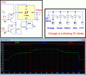
Finally, with the fantastic help from coolet, here we are:
Schematics are available here (Sorry, parts had been renumbered):
www.esperado.fr - Protection d'amplificateur ultime
You can get the full schematic at once here:
http://www.esperado.fr/images/stories/protection/ESPERADO_PROTECT_v3..gif
Various data-sheets available here:
Index of /images/stories/protection/datas
Inside this folder, you can access to BOM:
BOM
I will make the same kind of stuff i made for schematics, for you can list automatically the parts you need according your options. Be patient, it is a lot of work.
Last edited:
Merci (thanks)Bien le bonjour Esperado!
Sacré boulot accompli!
Amicalement!
Member
Joined 2009
Paid Member
Finally, with the fantastic help from coolet, here we are:
Schematics are available here (Sorry, parts had been renumbered):
It is a tour de force

Any error signal of a duration >= 1µs will fire the mosfet in a delay of 7µs for complete cut (from the start point of the error, with a transition time <1µs and a duration of 5sec.
All is accessible from the page:
www.esperado.fr - Protection d'amplificateur ultime
With BOM and linked datasheets, descriptions of functions, measurements, schematics, and spice simulation file + models.
Enjoy.
All is accessible from the page:
www.esperado.fr - Protection d'amplificateur ultime
With BOM and linked datasheets, descriptions of functions, measurements, schematics, and spice simulation file + models.
Enjoy.
Attachments
I'm not very satisfied by the response at very high frequencies (> 10Mhz). This is due to the response time of the LM339.
I want your tweeters to be protected whatever happens.
We will replace the first tempo by schtottky rectifiers. First tests are promising. All the rest is working as expected. This will remove some comparators. It will be a mix between the first version and the last one.
I want your tweeters to be protected whatever happens.
We will replace the first tempo by schtottky rectifiers. First tests are promising. All the rest is working as expected. This will remove some comparators. It will be a mix between the first version and the last one.
Little improvements for better oscillation detection at very HF:
Added little caps in // to R15/R16 to increase sensitivity @ 10MHz, and reduced impedance of the feedback loop of the U3, U4 OPAS.
V4.01 : www.esperado.fr - Protection d'amplificateur ultime
Because error detection is made by schottky diodes, now, nothing to worry about the slewrate of those OPAs. We can use any high bandwidth ones, now.
Time for PCB Layout.
Last edited:
All the parts not in red can be SMD's. I'm not experienced to them (size, references etc) One of the reasons why i need help for the PCB. The other one, is there is decades i have not used Eagle, and it will be a lot of work to re-learn it from scratch.Now as much as these parts have to be SMDs and merged together in a small double sided PCB. That would be a next big task to finish the project.
There is an other question i ask myself, it is to know what is better, using a quad OPA for the 'U's, or two double ones, for having more choice of OPA references.
Too, in order to make an overkill protection against any oscillations in power amps, we need some experience from various users. To figure-out the practical gain range for U3, U4 on various power amplifiers, in order to chose the best OPA for this purpose: some 140Mhz ones, by example, are stable if gain is > 25.
Well, i got no help for the PB design, it seems this project does-not interest people over here. A lot of work from my side for NO practical result. I was dreaming it was possible to build a collaborative project, on an original, innovative with very efficient results (>100 time faster than anything similar in the market), i was mistaken. No need to say how much i'm disappointed.
Have a good life, i will kill the web pages soon.
Have a good life, i will kill the web pages soon.
Last edited:
- Status
- This old topic is closed. If you want to reopen this topic, contact a moderator using the "Report Post" button.
- Home
- Amplifiers
- Solid State
- An ultimate amp protection circuit ?


