Christophe,
That Thermistor looks like it is specifically intended to go into a liquid bath of some kind. Why not just a thermocouple rather than the thermistor? Or is there a thermistor for direct contact to a metallic substrate that would be better suited to your purpose?
That Thermistor looks like it is specifically intended to go into a liquid bath of some kind. Why not just a thermocouple rather than the thermistor? Or is there a thermistor for direct contact to a metallic substrate that would be better suited to your purpose?
Christophe,
That Thermistor looks like it is specifically intended to go into a liquid bath of some kind. Why not just a thermocouple rather than the thermistor? Or is there a thermistor for direct contact to a metallic substrate that would be better suited to your purpose?
Thermocouples produce a very small signal compared to thermistors in a given circuit.
It is always difficult, time consuming, and not beautiful to fix disk thermistors on radiators.Christophe,
That Thermistor looks like it is specifically intended to go into a liquid bath of some kind. Why not just a thermocouple rather than the thermistor? Or is there a thermistor for direct contact to a metallic substrate that would be better suited to your purpose?
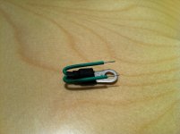
Here, just a simple hole in it, and the cable is fixed, no need to be isolated, fixed etc.
And thermal contact will be better, i presume.
Well, the last circuit, not fully verified, some values of resistances are subject to changes.
Added the command for fans, low speed at 55° (will cut once down at 45°), and hight spped at 75° (will return slow at 65°, and the alarm+ protection fired at 90° ream once at 80°.
Attachments
K1 is a low inertia tempo witch increase the duration of the error pulse of >1ms, enough to fire 100% the 5sec. delay before the amp can rearm after a failure. Those tow circuits together will transform a pulse of 0.77µs in a pulse of 5 seconds, impossible to make with only one with such a speed.
Two circuits has been added, reading the CTN voltage drop, to fulfill L.C. requirements. When the output goes down at 0, it will reduce the impedance of the bottom part of the comparator's bridges, in such a way to ensure 10° of hysteresis before it can goes up again.
Two circuits has been added, reading the CTN voltage drop, to fulfill L.C. requirements. When the output goes down at 0, it will reduce the impedance of the bottom part of the comparator's bridges, in such a way to ensure 10° of hysteresis before it can goes up again.
Attachments
Last edited:
It is always difficult, time consuming, and not beautiful to fix disk thermistors on radiators.
It's simple, look what I did, also similar ready made are available.
")
Attachments
One more remark, remote power-on trigger voltage section has to be completely isolated from protection circuit's GND to avoid ground loops interference currents, also in a case of a general failure remote device will send mains current, or a big surge if storm lightning will break through. 
I was tempted to ask if we are also protected against floodsOne more remark, remote power-on trigger voltage section has to be completely isolated from protection circuit's GND to avoid ground loops interference currents, also in a case of a general failure remote device will send mains current, or a big surge if storm lightning will break through.
It is, ground will not bo on the circuit, you are right, it is not clear on the schematic. More than that, the optoisolator is protected against over-voltage over-current and can accept any signal between 5V to 30V.One more remark, remote power-on trigger voltage section has to be completely isolated from protection circuit's GND
http://www.esperado.fr/images/stories/protection-totale-definitive.gif
Oh, it was on the schematic in the first page, not updated in the last design: You will like-it.
Attachments
Last edited:
!!!!! Final Version
FINAL VERSION, ready for a printed board design.
Thanks to all who helped to achieve this ultimate protection circuit.
Schematics are here:
www.esperado.fr - Protection d'amplificateur ultime
With a nice tool to play with the different parts of it and choose your version. Fans need the temperature alarm to work.
Coming soon: BOM.
Enjoy.
FINAL VERSION, ready for a printed board design. Thanks to all who helped to achieve this ultimate protection circuit.
Schematics are here:
www.esperado.fr - Protection d'amplificateur ultime
With a nice tool to play with the different parts of it and choose your version. Fans need the temperature alarm to work.
Coming soon: BOM.
Enjoy.
Last edited:
Diagram still has many problems.
Many resistors with no designator. Resistor footprints? 1206 125mW, 0805...
Many diodes including zeners with no designator and no part number.
Many parts (ICs) with no pin numbers.
Inconsistent and incorrect use of multiplier suffixes (K for k, E for R).
Inputs/outputs not distinguished. 'To Amp-in left.' Output? Pin? Socket? 'In left.' What is 'In left'? Input? Output? Pin? Jack? With ground, or signal only?
Transistor designator - Q1 Q2 Q3...
IC designator U1:A U1:B U1:C... U2:A U2:B ... U3...
Transformer on the PCB? If not, what connectors? If yes, part number, footprint. VA rating, primary voltage, secondary voltage?
Circuit description? Any special considerations? Double or singlesided with links? Track widths or power? Multipoint, star or linear grounding? Ground plane? Parts to be kept together? Parts to be kept apart? LED locations? Heatsinking? Components one side or both sides? Desired PCB dimensions or mounting points?
I can fix all these things, but it is more work than designing the circuit.
Man, it is intended to be a collaborative project.... Inconsistent and incorrect use of multiplier suffixes (K for k, E for R)....
This is not a commercial project, neither, you know: 'do it yourself'. or, please, wait for a final board, or/and BOM.
Don't you have something more intelligent or useful to do that look at the size of the K or E instead of R (due to two different graphic programs used by two different people with different habits) ?
Still waiting for the final design of coolet, (THanks a lot to him
) with renumbering, but everything is here, i believe, to begin a printed board design.Resistors have no power rating requirements, reason why no one is marked with 'w'.
Diodes are obvious too (you know what are diodes for 1.5A power supply and signal diodes ?)
Connectors ? Feel free to chose the ones you want or just holes for welded wires, as you prefer. No connectors for speakers wires: big diameters, will be welded.
What the hell this story of inputs have to do with the printed board ?
The transformer is not supposed to be on the board (as indicated) , because this is intended to be used inside amps, too, witch can have their own +-12V.
Pins of the CIs are all standard, you can chose witch OPA or comparator in the quads to facilitate the paths.
¨Track widths" ? Good question.
The only important are the speakers and power supply ones (to the power amp). They have to be as short as possible, just near the relays, for the speakers, and can be surcharged with coper wires or weld for no parasitic 'Z'.
There is only *one* LED in the circuit, used like a Zener.
The parts in reds are through holes, all the others can be SMD, may-be T1 T2 too.
Some data-sheet available here: Index of /images/stories/protection
The only part witch require an explanation, on my opinion, is the power fets used for the loudspeaker mosfet relay . There are 3 standard one, but (if possible) one need to can be replaced by a IP8025N10N3 (data on my site) witch has a different foot print.
Zeners Z1, Z2 are 5W axial ones: for example: 1N5378B. (this can vary according to the power amp to be protected).
Last edited:
OP4 does not cutoff, if you worry about the power amp trasfo's inductance. It is opened at start-up and shunt the current limiter (NTC or power resistance ).For OP4, zero crossing is not preferred.
It's simple, look what I did, also similar ready made are available.
I use this thermostats, mainly the TO-220 version:
Thermostats | Farnell United Kingdom | Results
Sajti
I use this thermostats, mainly the TO-220 version:
This is bi-metal switch, on-off function at certain temp.
Mine is NTC thermistor, linear measuring part, resistance in linear relation to temp.
This is bi-metal switch, on-off function at certain temp.
Mine is NTC thermistor, linear measuring part, resistance in linear relation to temp.
I think that this thermostats are the perfect parts for protection. As simple, as possible. I use the "L" prefix, which simply remove the power from the output relay in case of overtemperature.
Sajti
Nice ones, but > 3 time more expensive, more mechanical work for 3 temps, and less flexibility on on/off temperatures.I use this thermostats, mainly the TO-220 version:
Thermostats | Farnell United Kingdom | Results
Sajti
An other source for us: http://www.epcos.com/inf/50/db/ntc_09/ProbeAss__B57500__501__K500__501.pdf
And, very cheap: http://www.farnell.com/datasheets/1344383.pdf
Last edited:
Nice ones, but > 3 time more expensive, more mechanical work for 3 temps, and less flexibility on on/off temperatures.
An other source for us: http://www.epcos.com/inf/50/db/ntc_09/ProbeAss__B57500__501__K500__501.pdf
And, very cheap: http://www.farnell.com/datasheets/1344383.pdf
These are even better for mounting to heatsink
B57045K0472K000 - EPCOS - THERMISTOR, NTC, RADIAL LEADED | Farnell United Kingdom
B57703M502G40 - EPCOS - THERMISTOR, NTC | Farnell United Kingdom
This one is very nice, did it exists in 10K ?These are even better for mounting to heatsink
B57045K0472K000 - EPCOS - THERMISTOR, NTC, RADIAL LEADED | Farnell United Kingdom
Nice ones, but > 3 time more expensive, more mechanical work for 3 temps, and less flexibility on on/off temperatures.
For 3 step temperature controll it's quite expensive, I agree. I use it for only for safety turn off. It's very reliable (what is the most important for protection use), easy to mount.
For -say fan controll- I use another small, and very cheap circuit, which controll the fan speed continously, as the temperature increase.
Sajti
- Status
- This old topic is closed. If you want to reopen this topic, contact a moderator using the "Report Post" button.
- Home
- Amplifiers
- Solid State
- An ultimate amp protection circuit ?