J'ai essayé de voir pour réaliser le dessin de la carte mais le circuit est très complexe et j'ai abandonné car je pense qu'il y à des gens beaucoup plus compétents que moi dans ce domaine sur le forum.
Mais je peux essayer de me repencher sur le problème sans garantir le succès car ce schéma le mérite.
Amicalement!
I tried to see to realize the design of the card, but the system is very complex and I left because I think there's a lot to people more knowledgeable than me in this area of the forum.
But I can try to revisit the problem of me not guarantee success for this pattern deserves.
Regards!
Christophe,
I wouldn't do that, perhaps the correct person has not read the thread that could really help with your board design. I am not qualified in the least to help out that way but have read the entire thread and thought what you were doing was very interesting. Perhaps a new thread asking for board help would get someone interested that loves to do board layout.
Steven
Esperado, for now please leave it like it is and certainly do not shut down the web pages. Complex projects, as your protection is, takes time especially on DIY basis, commercially (faster realization) this protection would have to be a part of some amplifier. But in practice no company gives any data in their specification about protection, its response time, etc., meaning the market is satisfied with what it is available. Certainly a guys having expensive speakers are the marketing target and they would be more than interested to have one of these implemented in their amplifier. Maybe some info in speaker's part of the forum would help too. 
I remember...But in practice no company gives any data in their specification about protection, its response time, etc.,
When i had this idea, i build a quick'n dirty board to demonstrate-it in my own amplifier. Then, i had an appointment with a young Hifi company, to try to sell them the idea.
Well, meeting-time with the company's guys: we put the amplifier under oscillo monitoring, and tried various accidents: oscillating amp, short cicuits etc...
Everything worked as expected, and , at the end of the demonstrations they asked questions, very interested about...
... my amplifier !
I'm not very hot to let this schematic open on the web, would do not like to see any Chinese company to stole this idea i want to keep free, and make profits with it.
Okay, because you asked-it, Andrej, i let-it open for one month more, hoping we can achieve, or at least advance on it all together...
http://media.kval.com/images/2006-11-28+The+Salvation+Army+Christmas+Kettles.jpg
An externally hosted image should be here but it was not working when we last tested it.
Last edited:

Christophe,
I wouldn't do that, perhaps the correct person has not read the thread that could really help with your board design. I am not qualified in the least to help out that way but have read the entire thread and thought what you were doing was very interesting.
Likewise.
Only one word to say: WOOOW (and thanks)........first try , not ready but work in progres ......@Esperado you have my help .......
Regards Alex.
So we really have one of the finest board designer on our side
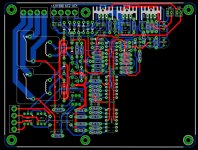
I suppose you will place the static relays on the other side of the board under the mechanical ones ? They where designed in a separated area in the schematics, but it was just for ease to read.
Well, if someone want to design a SMD version, it would be a good idea too in order to keep this circuit as little as possible. (But Alex is making-it so compact that i ask myself the question)
The components witch need to stay traditional (not SMD) are in red in the schematic. Or because they need to be adapted to various amps, or because they are optional.
Thanks to everybody for your support, i'm sure now that i was mistaken and that we will achieve this project all together.
iaxxaxxai, you board is very nice and compact, of course, you are welcome too.
Last edited:
Man, you definitively are an artist, and a fine electronician as well. It looks like a real piece of art........ Have spent some time to layout with SS relay on output .... lot of work .
I can imagine the time you have spend on this: Thanks, thanks, thanks.
Love a lot of your ideas: making the design to suit both SMD and traditional discreet components is brilliant. AC lines nicely isolated, radiator when use of a single static relay for HP output, can be useful on high power amps, the command for advanced FANS in-board, .... and a lot of nice details everywhere.
The only thing witch is missing, on my point of view, is outputs for mechanical relay coils, letting the user free to use some, as a choice or in addition to the static ones. Thinking to that, and because it is hard to find a standard dual contact relay available everywhere, it looks like a good idea to let them (mechanical relays) on a separate board or directly wired on their pins ?
And, a proper AC decoupling of the LT 1395 (noted 1365, 2X0.22µF) right on their power pins (can be other side of the board than the IC). For the comparator, i think it is enough as it.
I will take time to verify what i can if you think so. Or did-you prefer i wait a little more for an other version ?
Again, i'm very thankful and impressed by the quality of you design:... as habit.
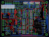
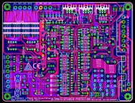
PCB rev 1.1 my version
Thank you Christophe , you are very kind . If I start , I can't be stop in my work . Ofcourse are mistakes and I hope somebody to find and I will correct .... please comment In place of SS relays will mount a small PCB with two normal relays , top of output area .


Regards Alex.
Thank you Christophe , you are very kind . If I start , I can't be stop in my work . Ofcourse are mistakes and I hope somebody to find and I will correct .... please comment
In place of SS relays will mount a small PCB with two normal relays , top of output area .
Regards Alex.
Attachments
Last edited:
To make this relay's story clear, if it helps-you in your choices, they can be used by audiophiles affraid by the evils of mos static relays. Unfortunately, as they take time to cut, the mosfets will cut first, and the mechanical relays will have all the amps to cut. Sparks in case of Amp's failure with full DC in output, with risk of reduction of contact's quality. Reason why i had chosen two contacts relays. This said, i doubt lot of people will use them because i see no need.
Nice idea to have them at the top of the board.
The two sharp AC relays do not need any radiator and are isolated on all their faces, so, can be mounted vertical if you prefer, but fine as-it.
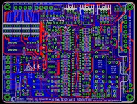
Oh, one thing is missing (my fault) : a ground to be added to the input's & outputs preamp connector (-> 5 pins) . It had to be as strait and short as possible to the ground of the elements (and your gently added decoupling caps ;-) of the LT13xx.
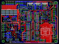
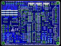
To be able to verify (i have to finish a debug on a program this night), i would need a version with the blue traces top, now, they are hidden by the red ones.
I will begin to-morrow night. If i can have outputs with only the components, too, i would be able to build populations for various versions, as i did for the schematic. Too, i will send-you the sources of the web pages if you like. It is your baby too, now.
btw: If it can help, tracks from "Remote from preamplifier" can be as thin and long as you like.
Ps: I'm not kind. "YOU" are really talented. I was very involved with the beauty (and accuracy) of printed boards designs, when i was in charge of this, and, looking at *all* your work is, each time, like listening to a masterpiece tune
Pure beauty, it grooves, it is full of love.
[Edit] you edited your post with all what i need to verify, thanks.
Nice idea to have them at the top of the board.
The two sharp AC relays do not need any radiator and are isolated on all their faces, so, can be mounted vertical if you prefer, but fine as-it.
Oh, one thing is missing (my fault) : a ground to be added to the input's & outputs preamp connector (-> 5 pins) . It had to be as strait and short as possible to the ground of the elements (and your gently added decoupling caps ;-) of the LT13xx.
To be able to verify (i have to finish a debug on a program this night), i would need a version with the blue traces top, now, they are hidden by the red ones.
I will begin to-morrow night. If i can have outputs with only the components, too, i would be able to build populations for various versions, as i did for the schematic. Too, i will send-you the sources of the web pages if you like. It is your baby too, now.
btw: If it can help, tracks from "Remote from preamplifier" can be as thin and long as you like.
Ps: I'm not kind. "YOU" are really talented. I was very involved with the beauty (and accuracy) of printed boards designs, when i was in charge of this, and, looking at *all* your work is, each time, like listening to a masterpiece tune
Pure beauty, it grooves, it is full of love.
[Edit] you edited your post with all what i need to verify, thanks.
Last edited:
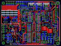
I will check this night. It is wonderful and so good looking.
But i believe you are not fully satisfied ;-)
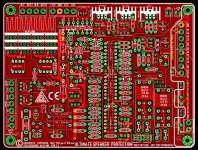
About the power mosfets, i think they do not need any radiator at all. Using one set of IP8025Nxx, and for an amplifier of 250Watts under 4 ohms, their power dissipation is < 0.16watts when on.
And, using only one set of IRF3710: <0.7 Watts.
So, if you forget the radiator, pushing down the mosfets, using, may-be mosfet drivers in surface mount version the other side, i think we can set the mechanical relay right between them and connectors.
As far i'm concerned, i do not care about those mechanical relays, i do not believe the mosfets to have any sonic influence, even in a high end "audiophile" system, and will not use them, so, for me, this last version is just perfect.
Man,, you have done an amazing work, and sooo fast !!!! As you says, no one can stop-you
But i believe you are not fully satisfied ;-)
About the power mosfets, i think they do not need any radiator at all. Using one set of IP8025Nxx, and for an amplifier of 250Watts under 4 ohms, their power dissipation is < 0.16watts when on.
And, using only one set of IRF3710: <0.7 Watts.
So, if you forget the radiator, pushing down the mosfets, using, may-be mosfet drivers in surface mount version the other side, i think we can set the mechanical relay right between them and connectors.
As far i'm concerned, i do not care about those mechanical relays, i do not believe the mosfets to have any sonic influence, even in a high end "audiophile" system, and will not use them, so, for me, this last version is just perfect.
Man,, you have done an amazing work, and sooo fast !!!! As you says, no one can stop-you
Last edited:
- Status
- This old topic is closed. If you want to reopen this topic, contact a moderator using the "Report Post" button.
- Home
- Amplifiers
- Solid State
- An ultimate amp protection circuit ?